NICA-MPD Detectors Subsystems
NICA Multi Perpose Detector
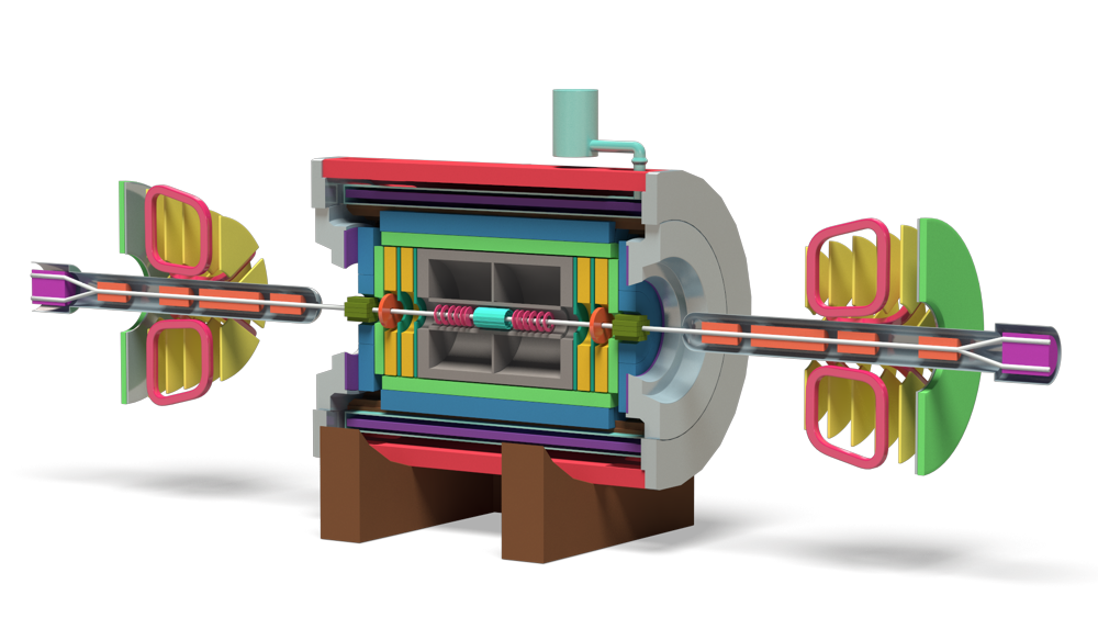
The MPD apparatus has been designed as a 4π spectrometer capable of detecting of charged hadrons, electrons and photons in heavy-ion collisions at high luminosity in the energy range of the NICA collider. To reach this goal, the detector will comprise a precise 3-D tracking system and a high-performance particle identification (PID) system based on the time-of-flight measurements and calorimetry. The basic design parameters has been determined by physics processes in nuclear collisions at NICA and by several technical constrains guided by a trade-of of efficient tracking and PID against a reasonable material budget. At the design luminosity, the event rate in the MPD interaction region is about 6 kHz; the total charged particle multiplicity exceeds 1000 in the most central Au+Au collisions at √sNN = 11 GeV . As the average transverse momentum of the particles produced in a collision at NICA energies is below 500 MeV/c, the detector design requires a very low material budget. The general layout of the MPD apparatus is shown in Fig. 1. The whole detector setup includes Central Detector (CD) covering ±2 units in pseudorapidity (η) .
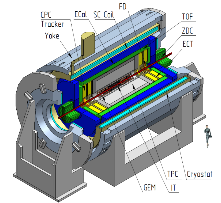
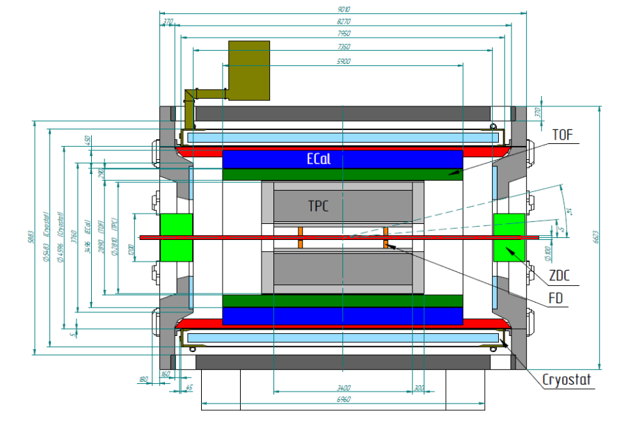
The aim of this Project is to build a first stage of the MPD setup, which consists of the superconducting solenoid, Time-Projection Chamber (TPC), barrel Time-Of-Flight system (TOF), Electromagnetic Calorimeter (ECal), Zero-Degree Calorimeter (ZDC) and Fast Forward Detector (FFD).
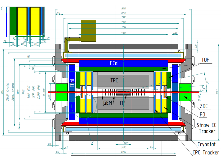
The layout of the first stage MPD is shown in Fig.3. The whole Central Detector (CD) will be a 9 m long cylinder of about 6,6 m in diameter. The cross-sectional view of the MPD Central Detector is shown in Fig. 2.
FS-A
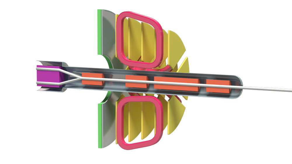
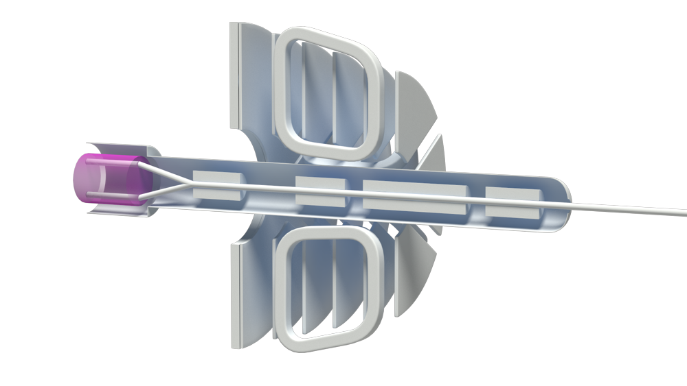
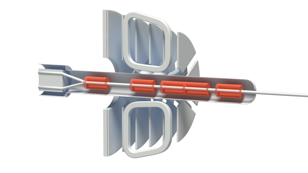
The FS’s are optional detectors which necessity will be defined after the CD became operational and first physics data are available. Those spectrometers should provide good momentum resolution and particle identification in the intermediate rapidity interval and large momentum region. There are considered two FS’s - A and B, allocated symmetrically along the beam line. Below we present some arguments in favor of forward spectrometers.
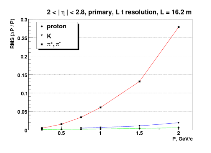
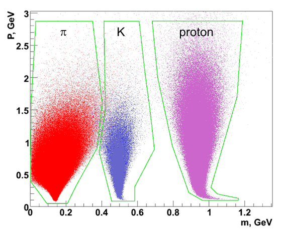
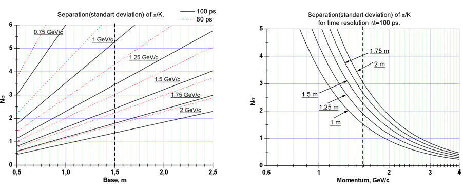
The particle momentum resolution of stand-alone CD in the region of pseudorapidity of η > 2 is deteriorated dramatically due to small value of ∫ Bdl. The information on the particle time-of-flight with hypothesis of particle type can allow for momentum reconstruction. It is evident that as longer time-of-flight base as better particle momentum determination. The result of such approach is presented in Fig. 1. However for pions the resolution is poor even with long TOF bases. The solution of the problem could come with introduction of magnetic spectrometer. The estimation of the momentum resolution of the magnetic spectrometer shows that if coordinate accuracy of track detectors is about 200 µm and track length in magnetic field is about 1 meter that allow momentum resolution better than 2%:
∆p/p = (σ/Lp2)(pp/0.2998B) p [720/(m + 6)].
m = 5 – number of measurements along the track
B = 1 T, σ = 200 µm, L = 1 m, p = 1 GeV/c ∆P/P ~ 1.7%
| Parameter | Value |
| etha coverage | (2.0–3.0) or (5–14) degree |
| magnet type | air toroid |
| nominal magnetic field | 1 T |
| spectrometer Z position | (7600–9800) mm |
| B × L | 1 T × M |
| number of coordinate layers | 10(2 × 5) layers |
| spatial resolution | ≤ 200 µm |
| track efficiency | about 99% |
| radiation length of layers | less than 5% |
| particles rate | 106 (average – 100 Hz/cm2, near beam pipe up to 1 kHz/cm2) |
| sensitive area | about 14 m2 per layer, 280 m2 in total |
1. link
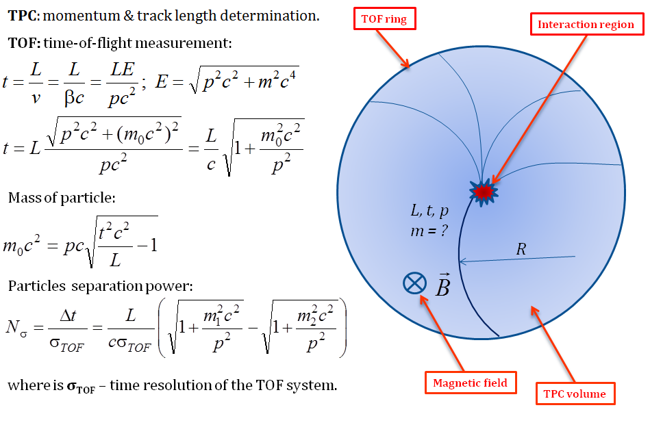
Time of Flight system
Ambitious physics goals of MPD require excellent particle identification capability over as large as possible phase space volume. Identification of charged hadrons (PID) at intermediate momenta (0.1–2 GeV/c) is achieved by the time-of-flight (TOF) measurements which are complemented by the energy loss (dE/dx) information from the TPC and IT detector systems.
The basic requirements to the TOF system are:
– large phase space coverage |η| <2;
– high granularity to keep the overall system occupancy below 10–15% and minimize efficiency degradation due to double hits;
– good position resolution to provide effective matching of TOF hits with TPC tracks;
– high combined geometrical and detection efficiency (better than 80%);
– identification of pions and kaons with 0.1 < pt < 2 GeV/c;
– identification of (anti)protons with 0.3 < pt < 3 GeV/c;
– TOF detector elements must function in a 0.5 T magnetic field.

1. link
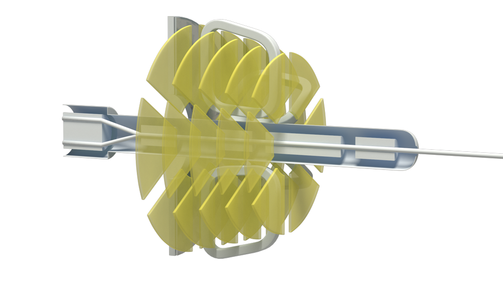
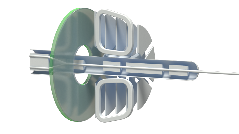
CPC Tracker
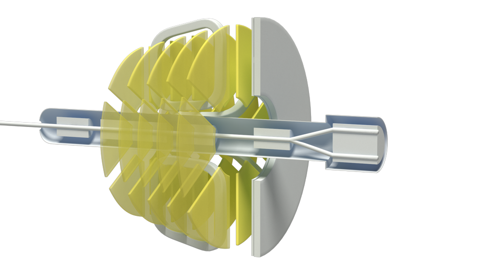
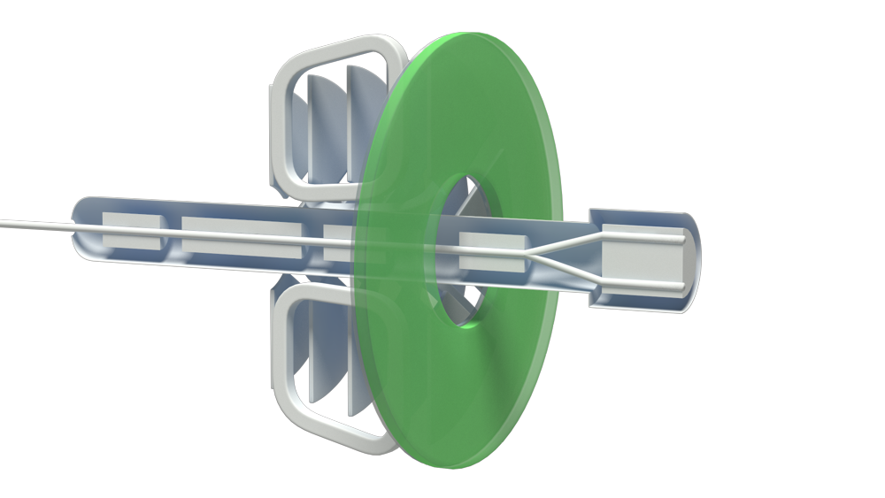
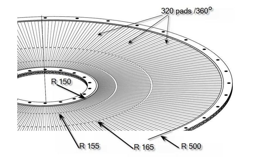
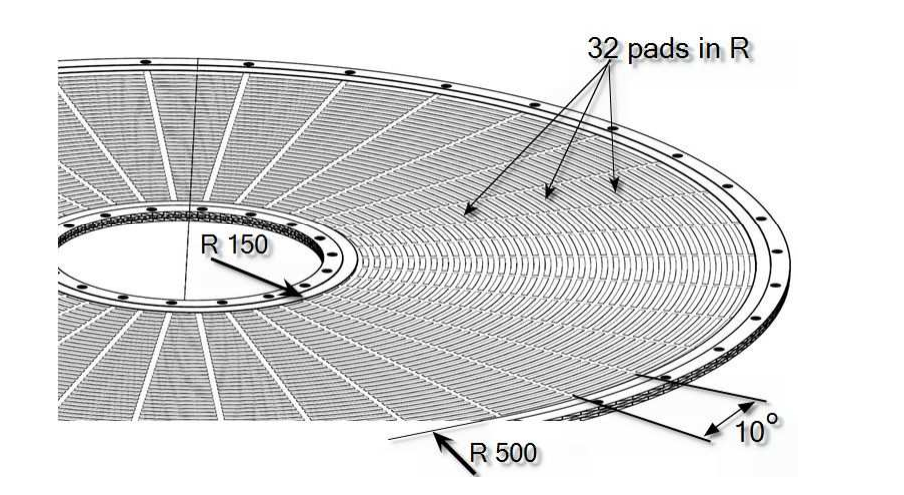
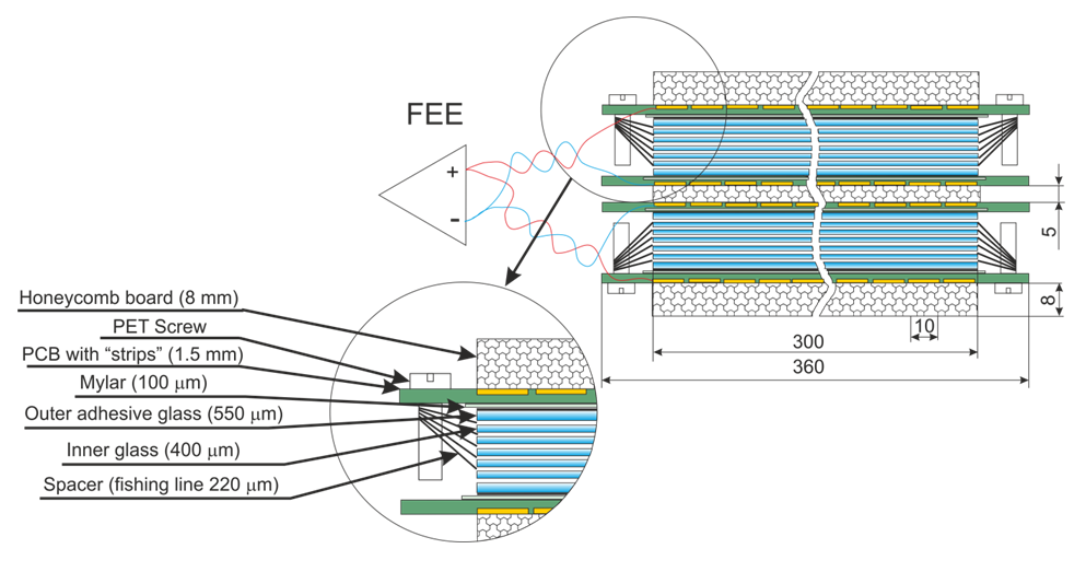
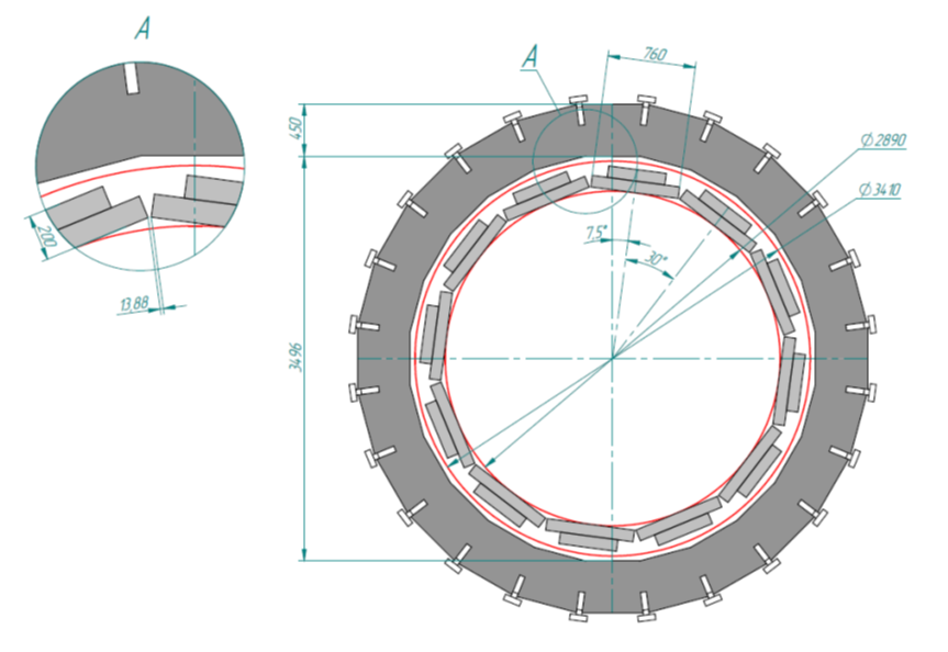
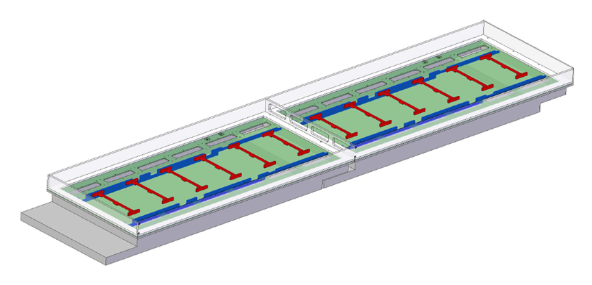
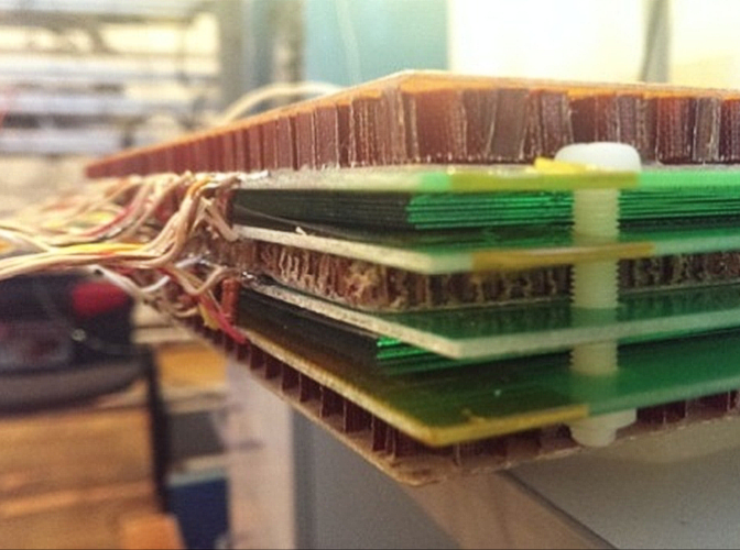
A conceptual design of the CPC of EC Tracker is shown in Figs. 2.110,2.111. The precise coordinate determination is based on the center of gravity measurement of induced on several neighbor pads charge. The inherent precision of the CPC comes from the lithographic process used in the etching of the pad structure. With this technique the pad position can be determined with a precision of about 15 µm.
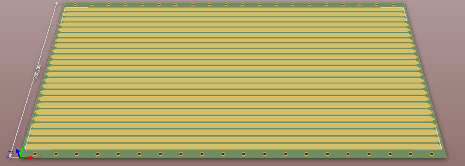
The basic elements for the CPC construction are a module panels. The procedure of module construction as follow:
— the high modulus skins of Carbon Fiber Composite (CFC) glued on both sides of 10 mm thick core of ROHACELL 31 HF [271] foam;
— to ensure the sealing of the gas box and its electrical shielding and grounding, a thin laminate of Kapton and Aluminium will be added to both sides of the panel;
— the FR-4 printed boards with cathode pad structure will be glued after that to both sides of the panel;
— at each end of the module panel, an insert will be glued, sandwiched between the two CFC.
Precision holes in the insert will permit the alignment of the panels during the detector - module assembly and provide the interface to the support system.
| Number of panels per chamber | 4 pc |
| Module panel thickness | 10 mm |
| Number of gaps per chamber | 3 |
| Gaps | 2 x 5 mm |
| Maximum outside diameter | 1060 mm |
| Frame width | 30 mm |
| Inner diameter | 240 mm |
| Coordinate planes | 6 (3 R,3 ϕ) |
| Wires per chamber | 400 x 3 |
| Wire diameter | 30 mkm |
| Wire pitch | 2.5 mm |
| Number of pads in R | 36 x 32 x 3 = 3456 |
| Number of pads in ϕ | 320 x 3 x 3 = 2880 |
| Chamber thickness | 70 mm |
| Space angle per chamber | 0.16 |
| Total material per chamber in active area | 0.028 X0 |
| Maximum number of charge particle per plane | 100 |
| Occupancy | less than 6% |
1. link
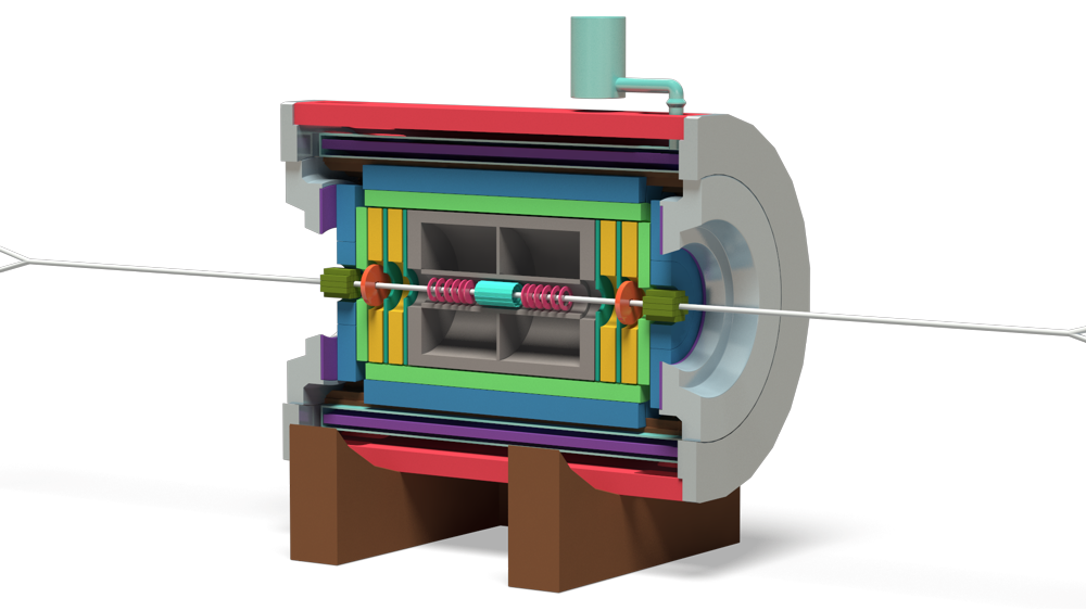
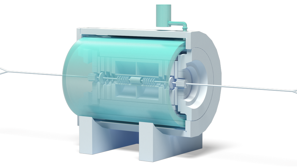
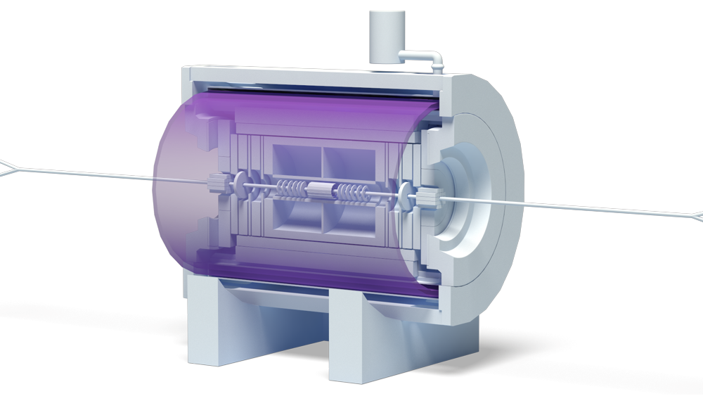
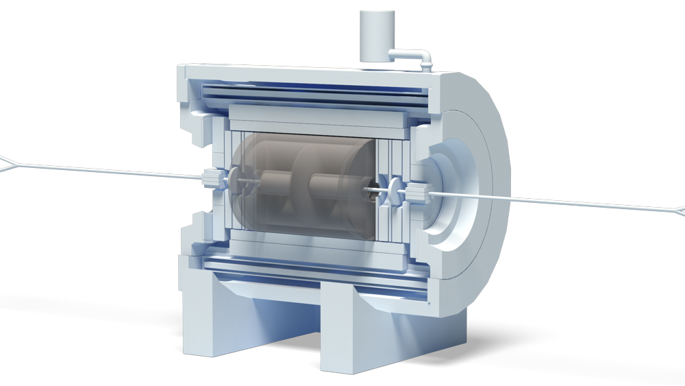
Cryostat
To obtain the assured thermal stabilization of the conductor, the cold mass is to be installed in the space between inner and outer cryostat vacuum shells and supported by high thermal resistance ties and struts. The coil is indirectly cooled by two-phase liquid helium flowing through an aluminum cooling tube, which is welded to the outside surface of the support cylinder. The cold volume is surrounded by the thermal shield supported from the side of the vacuum chamber, which is cooled by helium gas at 40-80 K.
The cryostat is equipped with radiation shield inserted between the coil and the cryostat outer can. The shield surface is covered by high purity aluminum foil to reduce radiation heat loads. About 30 layers of superinsulation separate the vacuum vessel walls from the shields. The data of the thermal load at the thermal shield multiplied by the safety factor 2 are presented in Table 2.8. The overall heat load at the level 77 K is expected not to exceed 734 W in the operational mode.
| Inner radius (warm bore), m | 2.0 |
| Outer radius, m | 2.3 |
| Length, m | 5.7 |
1. link
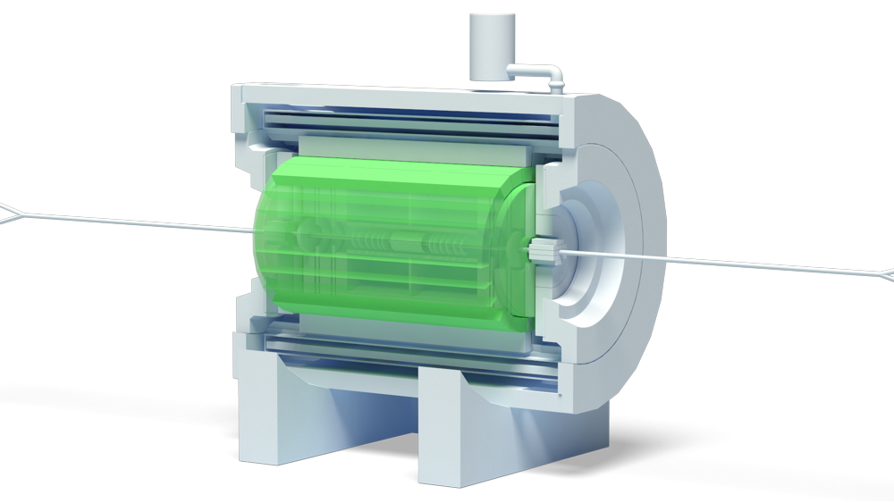
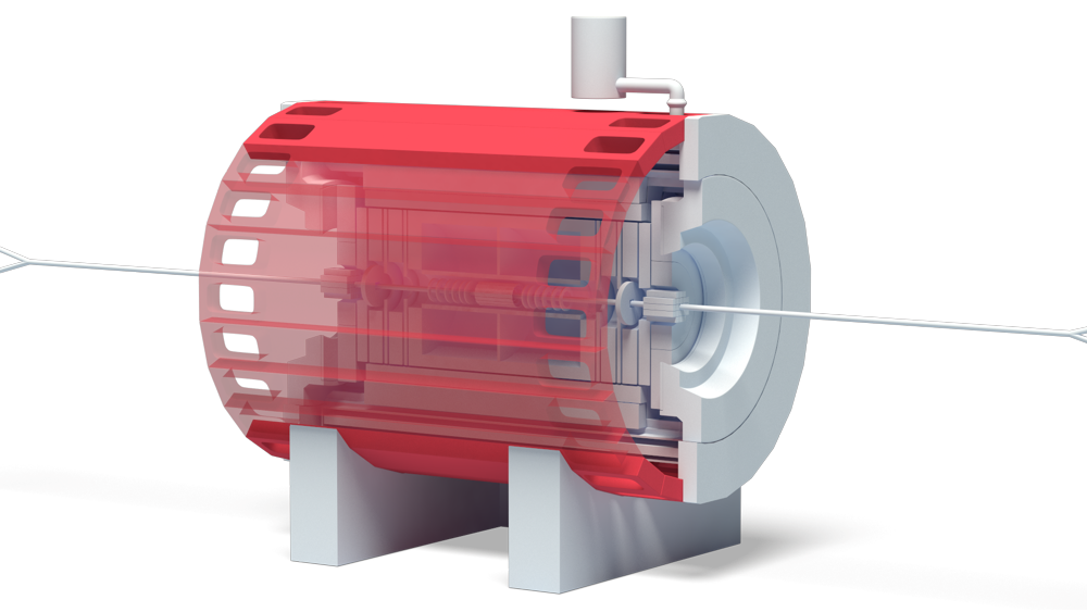
ECal
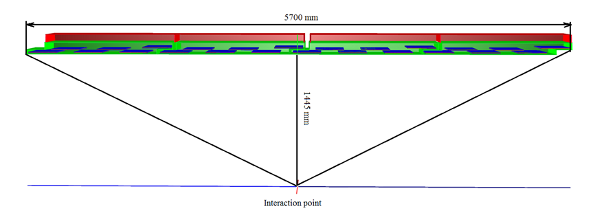
The whole barrel part of MPD electromagnetic calorimeter will be constructed from 48 sectors (Fig.1). The heat-producing electronics will be thus separated from the modules and mounted on the upper parts of sectors.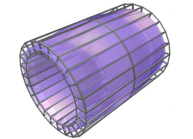
1. link
FD Tracker
Main aims of the FFD are fast determination of a nucleus-nucleus interaction in the center of the MPD setup. Besides, there are some additional important tasks where FFD is a useful instrument. It can much help in adjustment of beam-beam collisions in the center of the MPD and operative control of the collision rate and interaction point position during a run.
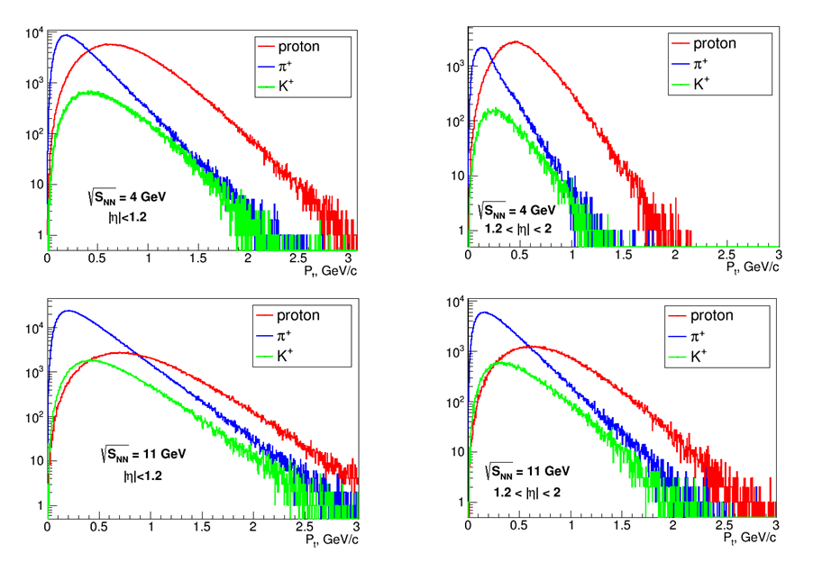
In comparison with experiments at ultra-relativistic energies at RHIC and LHC, there are two essential difficulties at the NICA energies. First, the charged particles produced in collisions mainly are not relativistic, and there is a large spread of spectator velocities which differ from the velocity of light (the beam velocities are in an interval 0.78 ≤ β ≤ 0.98). Second, the particle multiplicity is much lower than one in the other collider experiments. As a result, for efficient trigger we need to cover a large acceptance and try to detect all particles with β ∼1 to achieve needed timing. It leads to conclusion that the trigger and timing detectors used in other experiments at higher energies are not an optimal solution in our case and do not allow to reach the requirements mentioned above. So, one has to develop another conception of trigger and timing detectors for the MPD experiment.
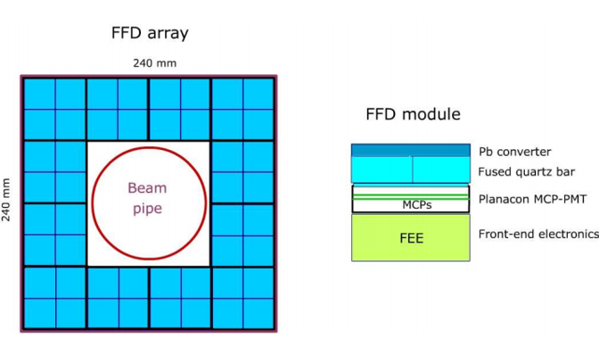
There is a well-known fact that central and semi-central collisions of two heavy nuclei at relativistic energies are characterized by multiple pion production. The neutral pions immediately decay with generation of many high energy photons passing the MPD subdetectors. The main idea of the FDD is to register a part of these photons at small angles to beam axis as the most suitable secondaries with highest and constant velocity. The proposed FFD design is a granulated Cherenkov detector which has a high efficiency for the high energy photons and for ultra-relativistic charged particles as well. The FFD consists of two sub-detectors, FFD-L and FFD-R, which are symmetrically placed to the MPD center along the beam line. Each sub-detector array has a hole for the beam pipe and locates at a distance of 75 cm from the center. Its acceptance in pseudo-rapidity is 2.5 ≤| η |≤ 3.2.
1. link
Time of Flight system
Ambitious physics goals of MPD require excellent particle identification capability over as large as possible phase space volume. Identification of charged hadrons (PID) at intermediate momenta (0.1–2 GeV/c) is achieved by the time-of-flight (TOF) measurements which are complemented by the energy loss (dE/dx) information from the TPC and IT detector systems.
The basic requirements to the TOF system are:
– large phase space coverage |η| <2;
– high granularity to keep the overall system occupancy below 15% and minimize efficiency degradation due to double hits;
– good position resolution to provide effective matching of TOF hits with TPC tracks;
– high combined geometrical and detection efficiency (better than 90%);
– identification of pions and kaons with pt < 1.5 GeV/c;
– identification of (anti)protons with pt < 3 GeV/c;
– TOF detector elements must function in a 0.5 T magnetic field.
| Number of detectors | Number of readout strips | Sensitive area, m2 | Number of FEE cards | Number of FEE channels | |
| MRPC | 1 | 24 | 0.2205 | 2 | 48 |
| Module | 6 | 144 | 1.08 | 12 | 288 |
| Sector | 24 | 576 | 4.19 | 48 | 1152 |
| Barrel | 288 | 6912 | 50.3 | 576 | 13824 (1728 chips) |
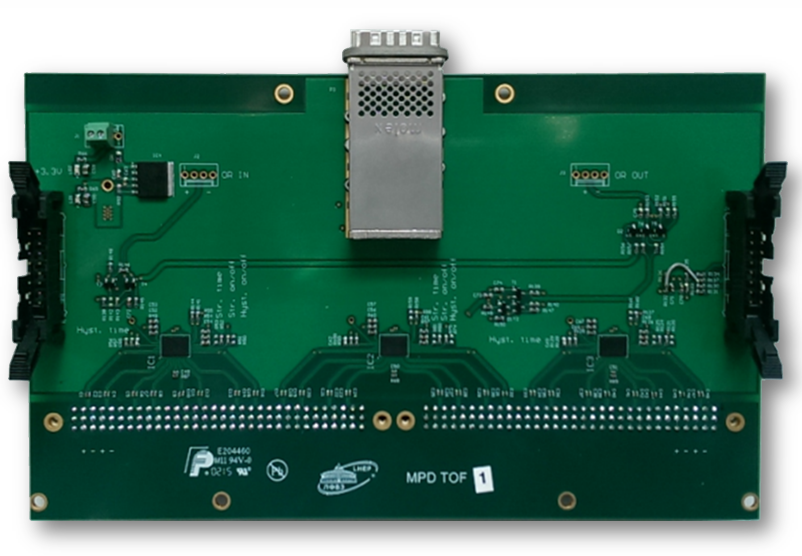
1. MPD NICA. Technical Design Report of the Time of Flight System (TOF) Laboratory of High Energy Physics, JINR, Dubna — V.A. Babkin, S.N. Bazylev, M.G. Buryakov, V.M. Golovatyuk, P.O. Dulov, D.S. Egorov, Yu.I. Fedotov, V.I. Kolesnikov, S.P. Lobastov, V.A. Petrov, M.M. Rumiantcev, V.M. Slepnev, I.V. Slepnev, A.V. Shutov, A.V. Shipunov, S.V. Volgin, N.M. Vladimirova,
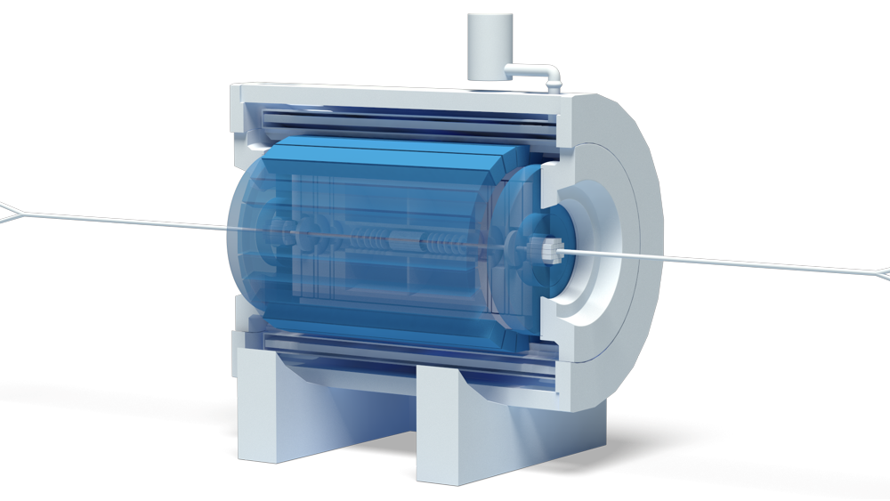
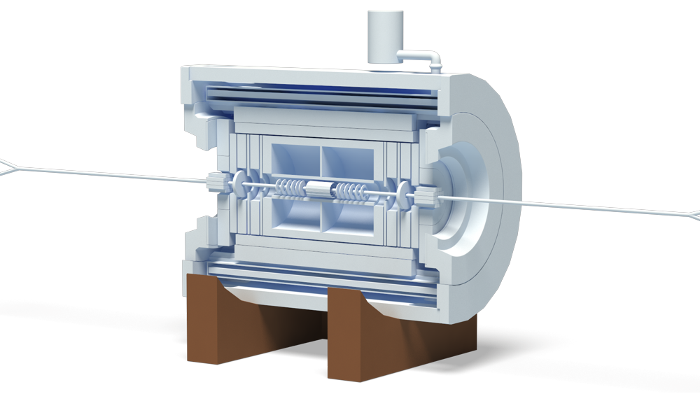
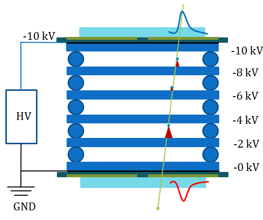
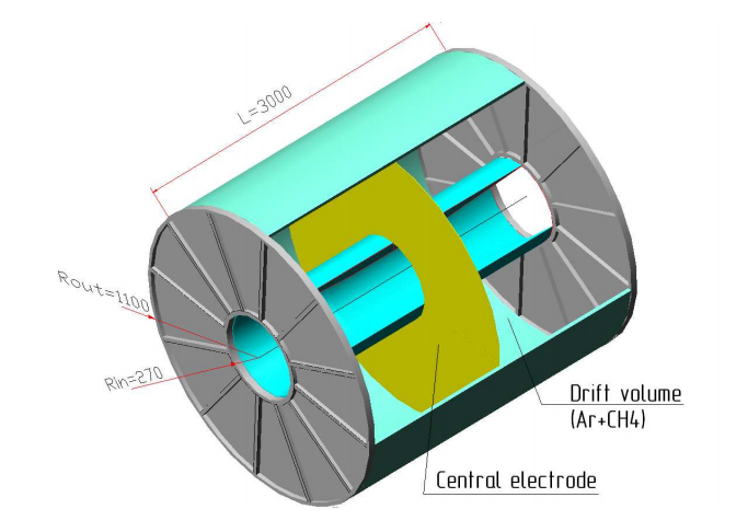
Time projection chamber
The MPD time projection chamber (TPC) is the main tracking detector of the central barrel and, together with the internal tracking system, time of flight system and electromagnetic calorimeter has to provide charged particles momentum measurement with sufficient resolution, particle identification and vertex determination, two track separation and dE/dx measurement for hadronic and leptonic observables at pseudorapidities |η| <1.2 and pt >100 MeV/c.
The electromagnetic calorimeter will provide, in conjunction with the data from the TPC, reliable electron identification to study dielectron processes. TPC has to provide the high dE/dx resolution in the high multiplicity environment of a Au + Au central collision to identify electrons with an efficiency of over 90% and reject pions at the level of 103.
The track reconstruction in the region of pseudorapidity beyond 1.2 is provided by both TPC and End cap straw tracker. In order to have excellent momentum resolution and identification capability in this region the end plate elements of the TPC and readout electronics which is mounted on them have to be minimized for material budget. Thus material budget of endplate and readout electronics is about 15%. The requirements to the TPC performance following from the physics described above are as follows:
— provide efficient tracking up to pseudorapidity region |η| =1.2.
— the momentum resolution for charge particles about 2% at the transverse momentum of 300 Mev/c.<.p>
— the two-track resolution has to be about 1 cm in order to provide interference measurements with a resolution in relative momentum of a few MeV/c.
— for hadron and lepton identification a dE/dx resolution better than 8% is desirable
| Item | Dimension |
| Length of the TPC | 340cm |
| Outer radius | 110cm |
| Inner radius | 27cm |
| Outer radius of the drift volume | 100cm |
| Inner radius of the drift volume | 35cm |
| Length of the drift volume | 150cm (of each half) |
| Cathode | Membrane at the center of the TPC |
| Electric field strength | ~140 V/cm |
| Magnetic field strength | 0.5 Tesla |
| Drift gas | 90% Ar+10% Methane at Atmospheric + 2 mbar |
| Drift velocity | 5.45 cm/µs |
| Drift time | ~ 28µs |
| Transverse diffusion | 230 µm/√ |
| cm at magnetic field | 0.5 Tesla |
| Longitudinal diffusion | 360 µm/√ cm |
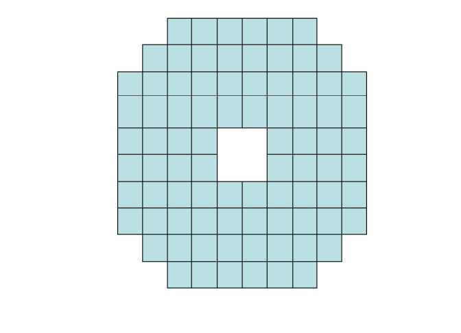
| Number of readout chambers | 24 (12 per end plate) |
| Multiplisity (central collision) | ~ 800 |
| Number of pads | ~ 80000 |
| Pad numbers after zero suppression | < 10% |
| Pad size | 4x10 mm in inner sector area 6×12 in outer sector area |
| Spatial resolution | σz ~ 1 mm, σx ~ 0.6 mm, σy ~ 0.8 mm |
| ∆E/dX resolution | ~ 8% (75 samples× 2 cm) |
| Maximum rate | ~ 5 − 6 kHz (Lum. 102cm−2s−1) |
| Electronics shaping time | ~180 ns (FWHM) |
| Signal to noise ratio | 20:1 |
| Signal dynamical range | 10 bits |
| Sampling rate | 12.5 MHz |
| Sampling depth | 350 time buckets |
1. link
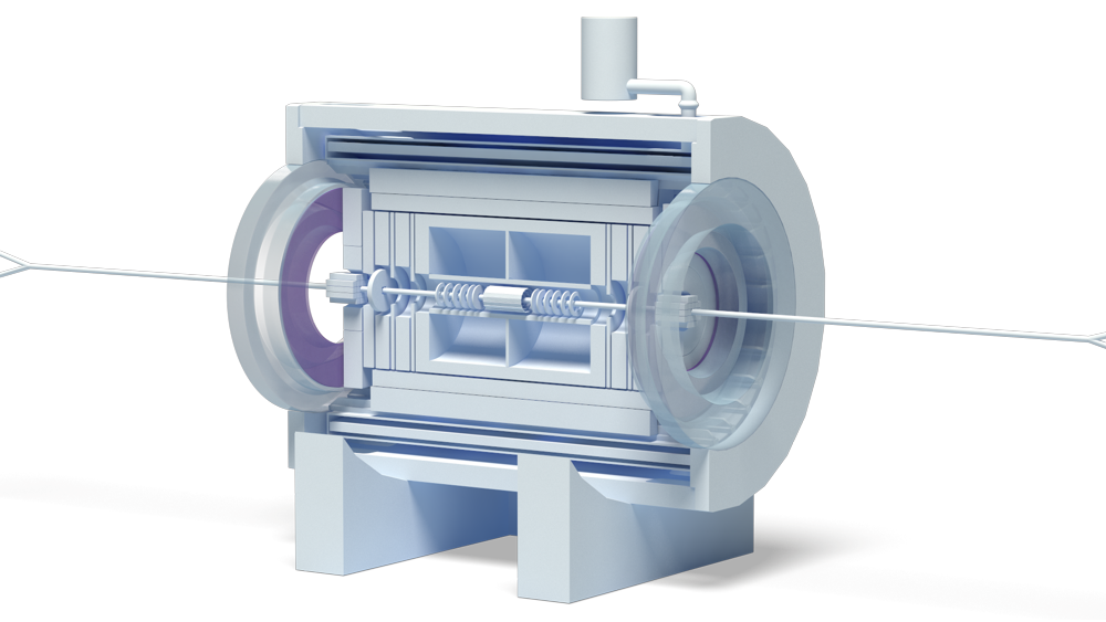
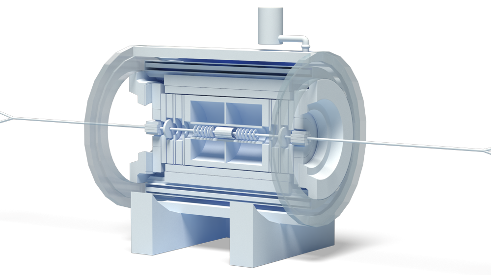
Yokes
The Solenoid iron yoke is a cylindrical steel structure consisting of 12 flux return bars, two supporting end rings, two pole tips and support structures. The 6 m long flux return bars are trapezoidal in cross-section, and weigh 17.2 ton each. They form the barrel part of the yoke, which contains the cryostat with the superconducting coil.
The supporting rings have a 4 m I.D., 5.34 m incircle O.D. and twelve chord surfaces on the 4.8 m diameter to control the azimuth and radial location of each flux return bar, with an axial thickness of 270 mm. A support ring weighs 20.9 ton each. Each pole piece weighs 28.4 ton and is fixated relative to the supporting ring. They have a conical 14 grad inner diameter, whole axial thickness 600 mm, a 3.9 m O.D. and a recess on the inner face surface for the trim coil. A 50 mm annular gap between supporting ring inner diameter and pole piece outer diameter is provided for passage of cables and tubing of internal detectors. To simplify manufacturing and transportation the poles are divided in axial direction on two parts consolidated by bolts which weigh about 14 ton each.
The solenoid support structure consists of two cradles weighing 17.5 ton each. They embrace the five lower flux return bars of the yoke barrel part. The support structure is placed on a transport carriage guided by two rails. The magnet traveling section (the magnet without both poles) can be moved between experimental hall and assembly area as required.
Two pole piece support structures weighing 31.7 tons each rest on rails so that the poles may be withdrawn to provide access to the ends of internal detector elements. All magnet yoke material is specified as Steel 10 which has a minimum yield strength of 210 MPa with an annealed heat treatment.
The magnetic field quality required that deflections in the magnet structure are to be minimized to less than 1 mm. This can be accomplished with precise fabrication of magnet components and the use of high strength bolted and pinned connections between mating components.
Yoke supports have to fixate the magnet at the foundation rigidly and to provide adjustment of the detector systems relative to the beam axis. To minimize the yoke deformations, five bottom beams will be welded-in to the yoke supports.
| Incircle radius of the yoke, m | 2.4 |
| Circumcircle radius of the yoke, m | 2.67 |
| Distance between pole tips, m | 5.24 |
| Length of the yoke, m | 6.4 |
1. link
Zero degree calorimeter tracker
The events classification by centrality of the relativistic nuclei collisions is a key topic of the experiments studying a strongly excited (hot and/or dense) hadronic matter properties. Obviously, the selection of central events is a necessary to study the most excited nuclear matter. However centrality classification not only separates central and peripheral events. Observables analysis in different centrality intervals appears very informative and allows to study space–time picture of the nuclear–nuclear collisions as well as hadronic matter properties, both of which impossible without centrality data involving. The importance of centrality classification can be illustrated by the following examples:
• The ratio of the elliptic flow to the space excentricity of the collision region is a constant for a wide range of the impact parameter, as it obtained at the RHIC experiments [273]. This fact as well as a great value of elliptic flow is a strong experimental indication for a small (≤ 1fm/c) thermalization time value. Such measurements are impossible without centrality classification of events, because space excentricity of the collision region is determined by centrality.
• For description of the Jet Quenching and J/Ψ suppression in nuclei–nuclei collisions the nuclear modification factor (RAA) is used. This factor depend from the number of binary collisions, which is determined by centrality.
Many examples of another observables, which requires centrality classification too, can be presented. However lets only note, that many current and planned relativistic nuclei collision experiments are paid essential attention to centrality extraction topics as well as measurements of the observables dependence on centrality (see and references in it).
1. link
FS-B
The FS’s are optional detectors which necessity will be defined after the CD became operational and first physics data are available. Those spectrometers should provide good momentum resolution and particle identification in the intermediate rapidity interval and large momentum region. There are considered two FS’s - A and B, allocated symmetrically along the beam line. Below we present some arguments in favor of forward spectrometers.
The particle momentum resolution of stand-alone CD in the region of pseudorapidity of η > 2 is deteriorated dramatically due to small value of ∫ Bdl. The information on the particle time-of-flight with hypothesis of particle type can allow for momentum reconstruction. It is evident that as longer time-of-flight base as better particle momentum determination. The result of such approach is presented in Fig. 1. However for pions the resolution is poor even with long TOF bases. The solution of the problem could come with introduction of magnetic spectrometer. The estimation of the momentum resolution of the magnetic spectrometer shows that if coordinate accuracy of track detectors is about 200 µm and track length in magnetic field is about 1 meter that allow momentum resolution better than 2%:
∆p/p = (σ/Lp2)(pp/0.2998B) p [720/(m + 6)].
m = 5 – number of measurements along the track
B = 1 T, σ = 200 µm, L = 1 m, p = 1 GeV/c ∆P/P ~ 1.7%
| Parameter | Value |
| etha coverage | (2.0–3.0) or (5–14) degree |
| magnet type | air toroid |
| nominal magnetic field | 1 T |
| spectrometer Z position | (7600–9800) mm |
| B × L | 1 T × M |
| number of coordinate layers | 10(2 × 5) layers |
| spatial resolution | ≤ 200 µm |
| track efficiency | about 99% |
| radiation length of layers | less than 5% |
| particles rate | 106 (average – 100 Hz/cm2, near beam pipe up to 1 kHz/cm2) |
| sensitive area | about 14 m2 per layer, 280 m2 in total |