STAR Detector

Magnet
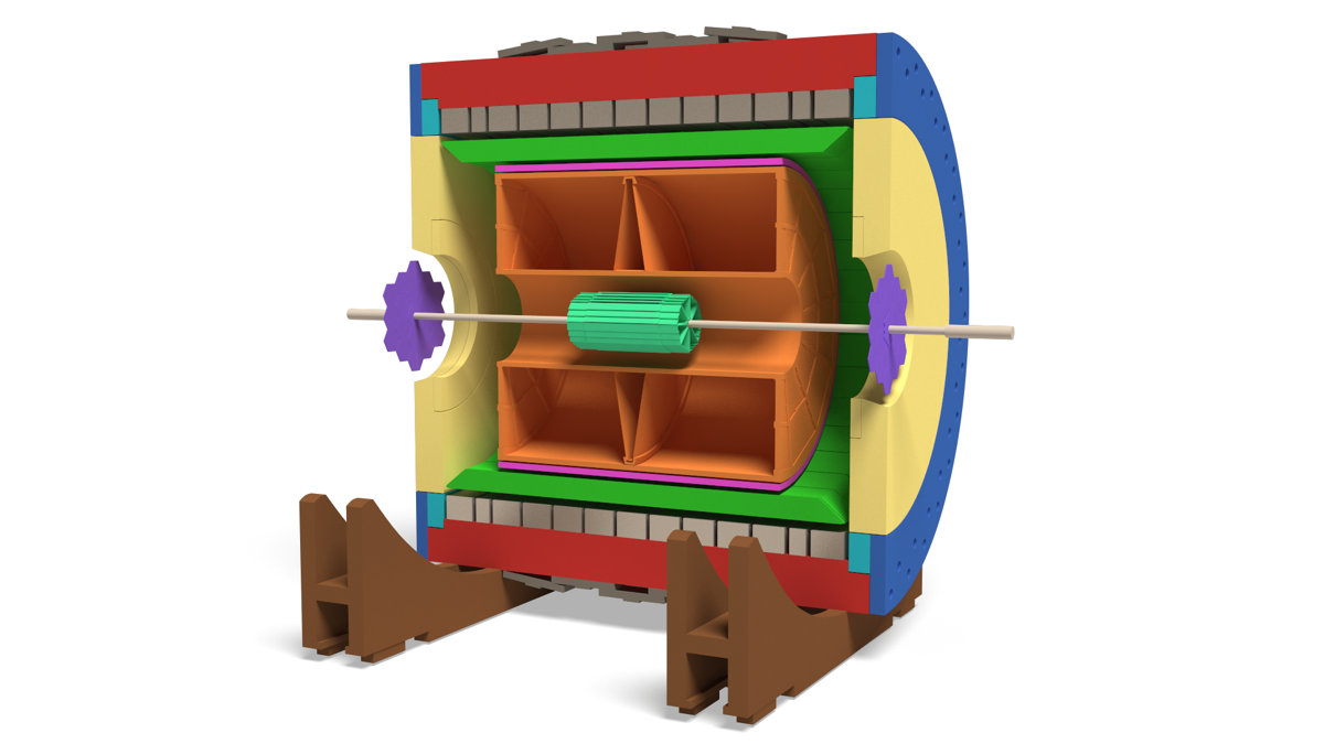
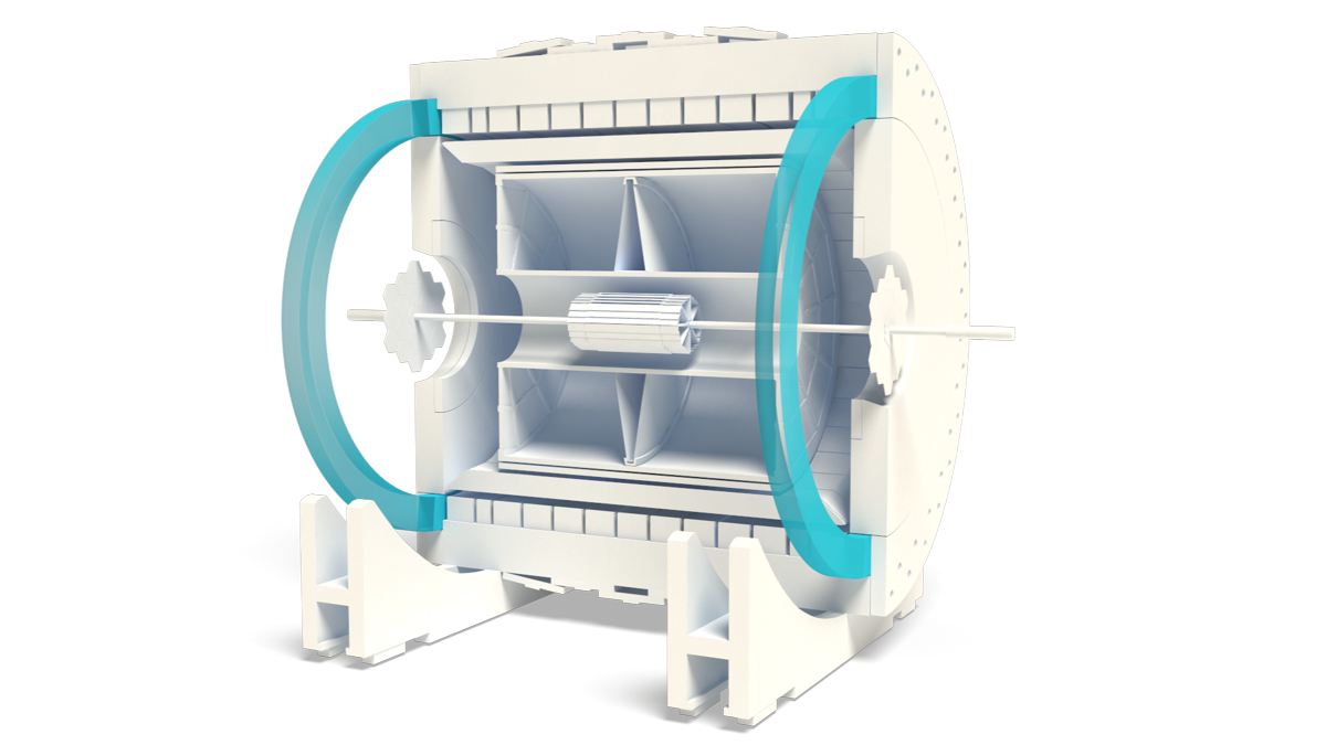
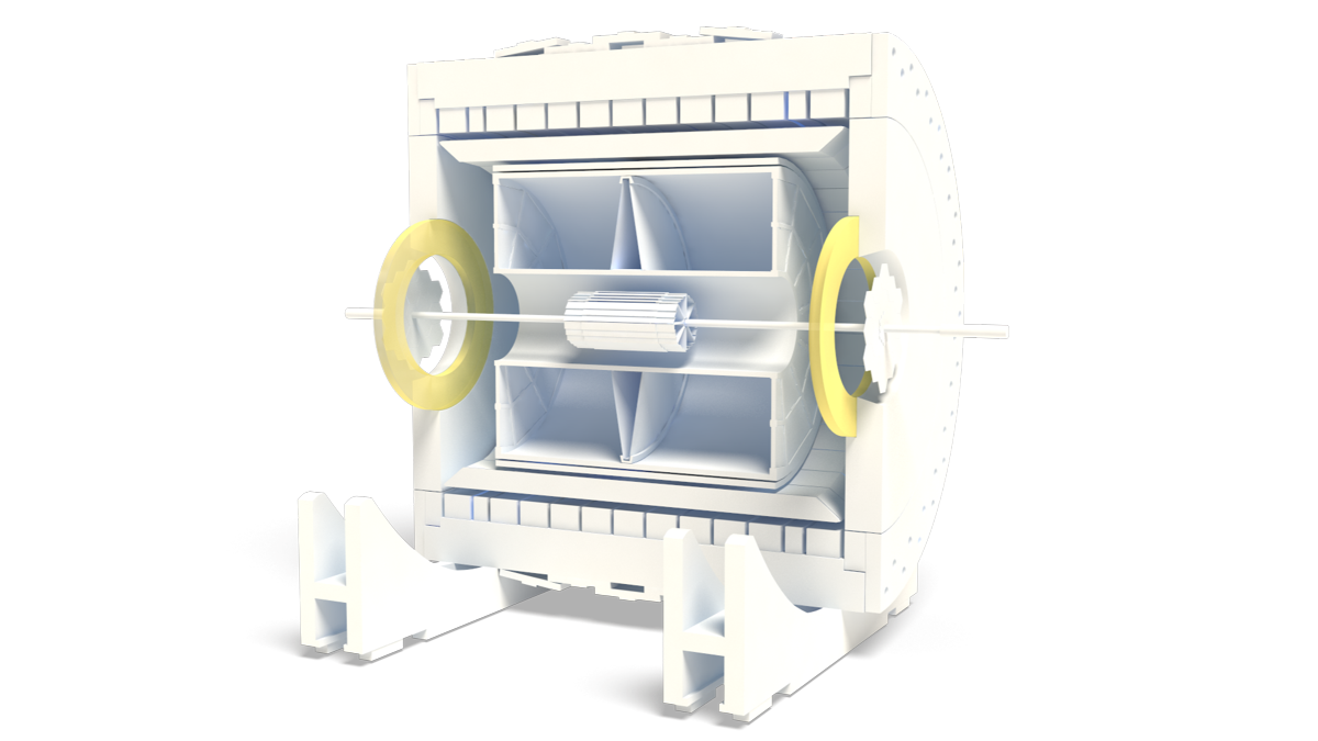
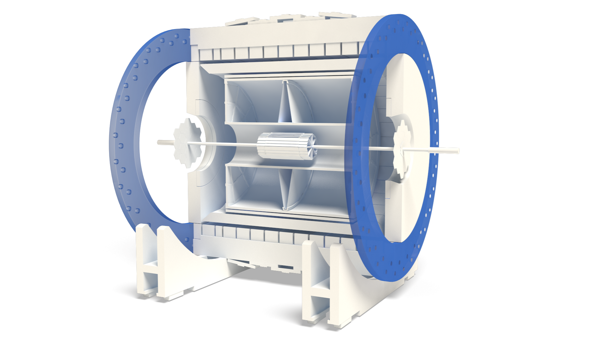
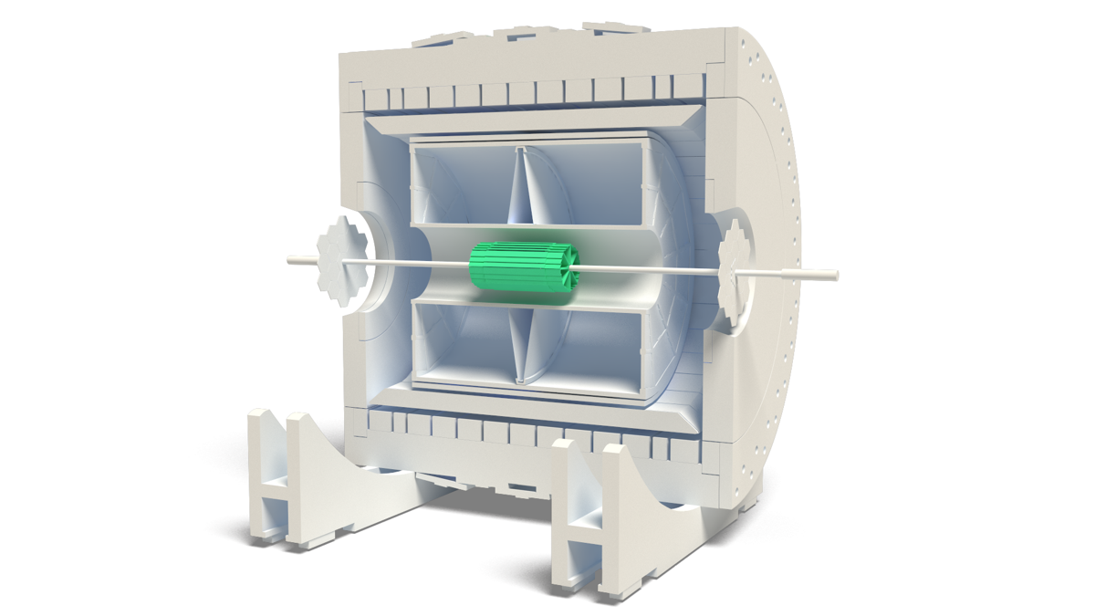
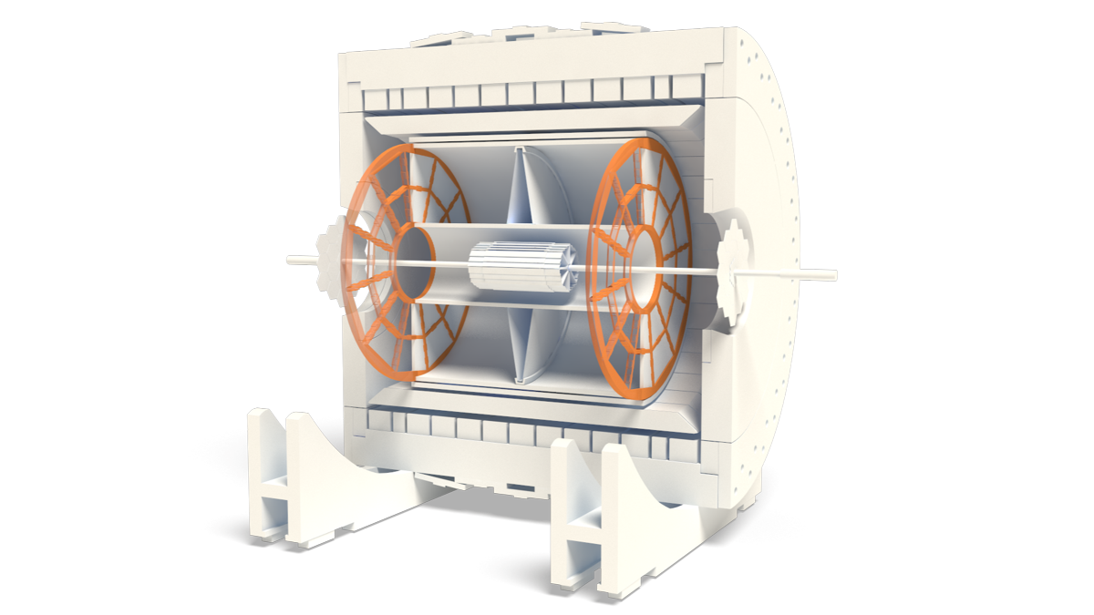
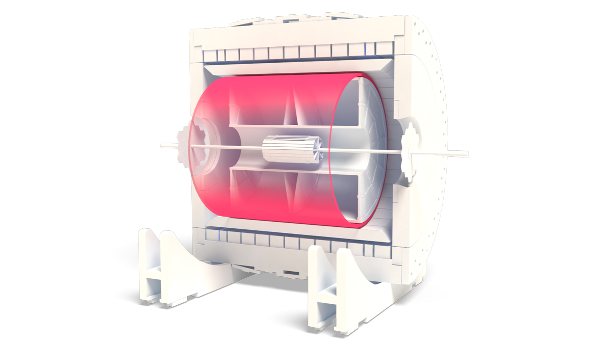
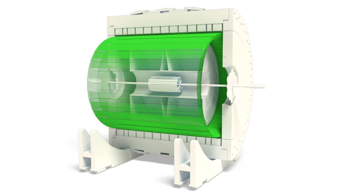
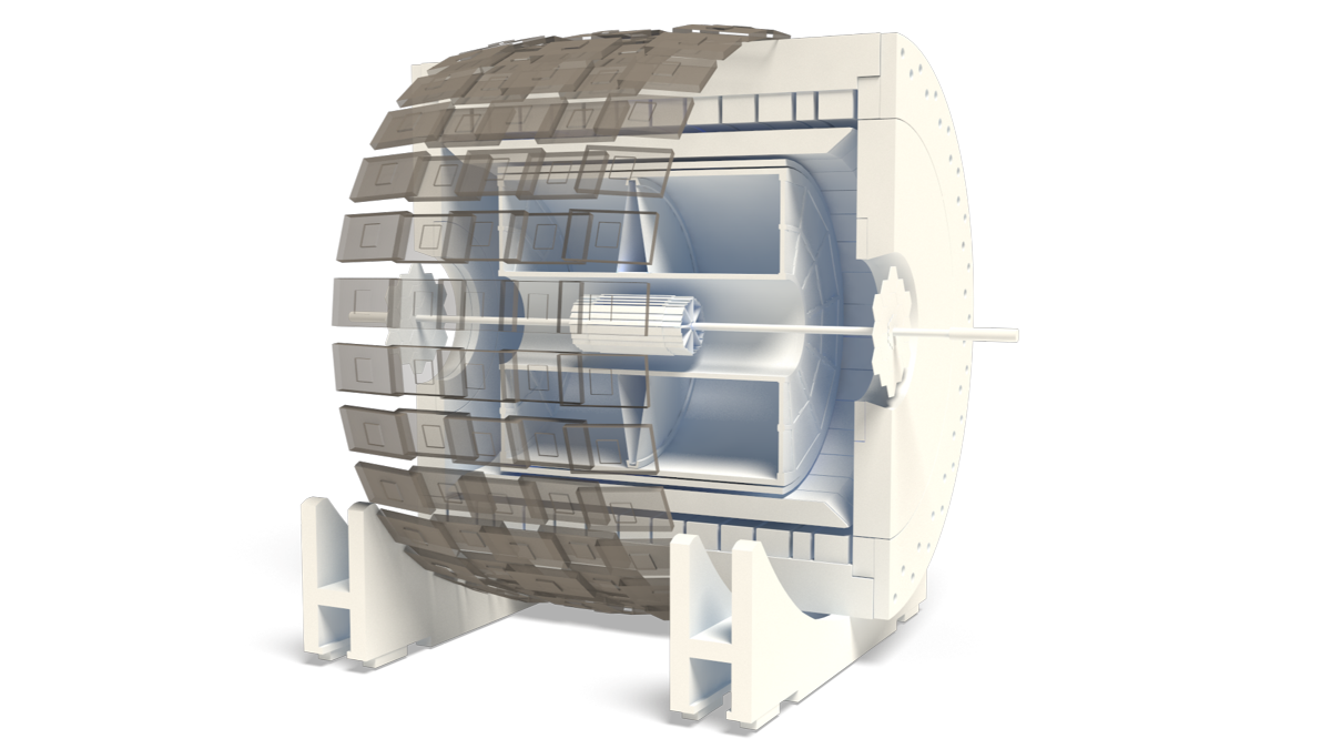
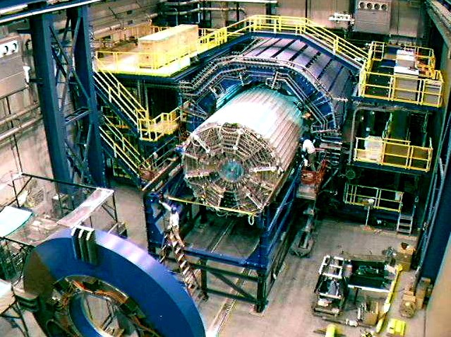
The Solenoidal Tracker At RHIC (STAR) search for signatures of quark-gluon plasma (QGP) formation and investigate the behavior of strongly interacting matter at high energy density. To accomplish this, a flexible detection system that can simultaneously measure many currently experimental observables is constructed. The system contains several subsystems such as the Time Projection Chamber (TPC), Heavy Flavor Tracker (HF), Forward Time Projection Chamber (FTPC) and the Electro-Magnetic Calorimeter (EMC). These subsystems operate in a magnetic field generated by the Magnet subsystem which is an iron dominated, conventional (room temperature) solenoid magnet. The field can be varied from 0.25 T to 0.5 T with a uniformity better than 1000 ppm over the entire TPC volume.
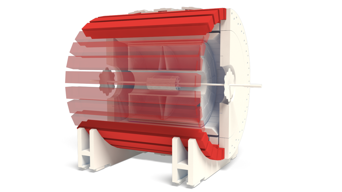
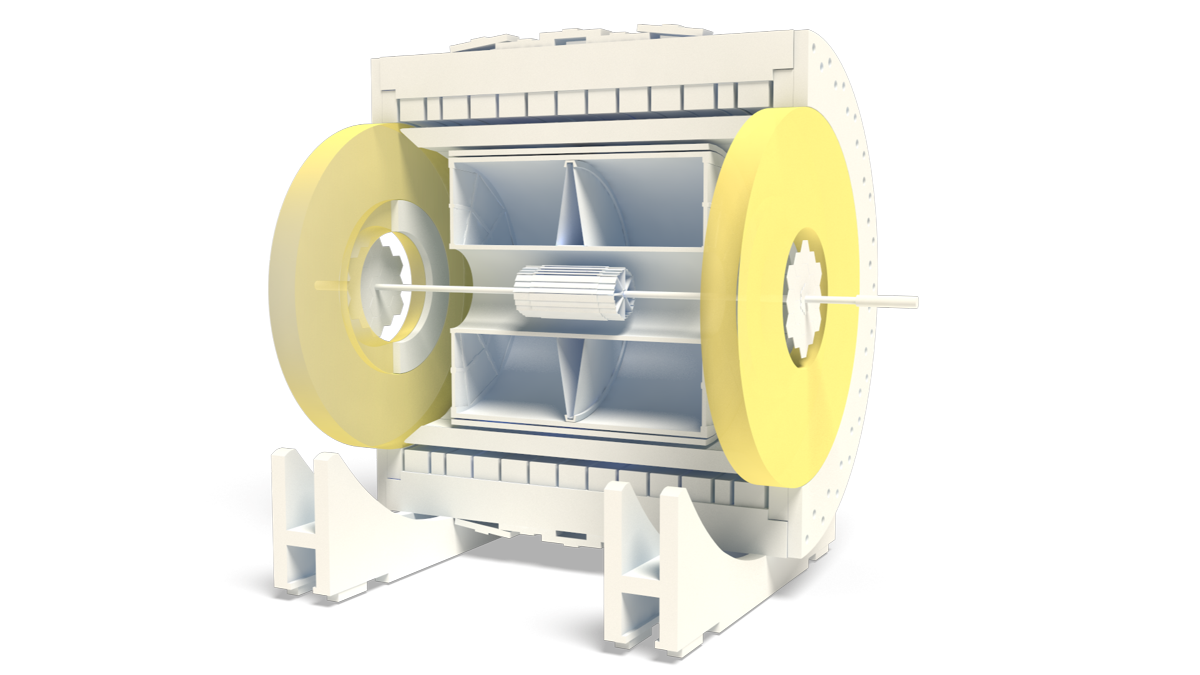
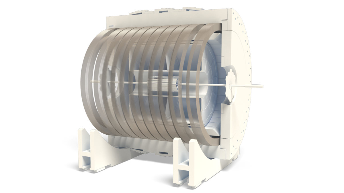
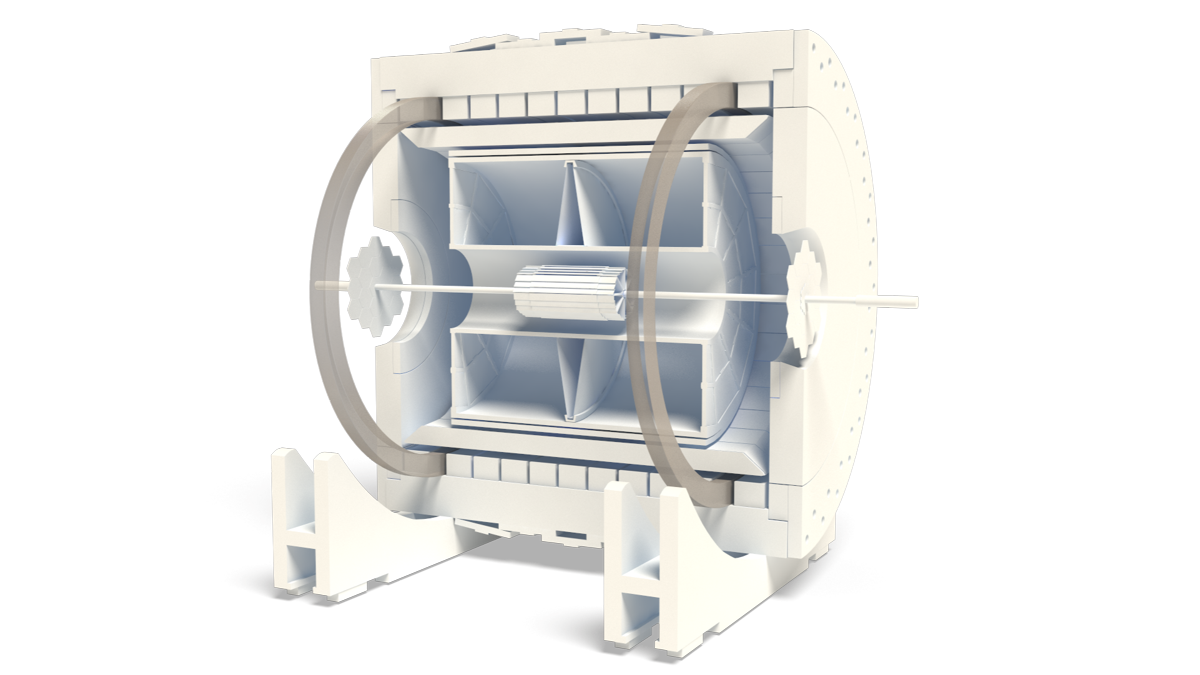
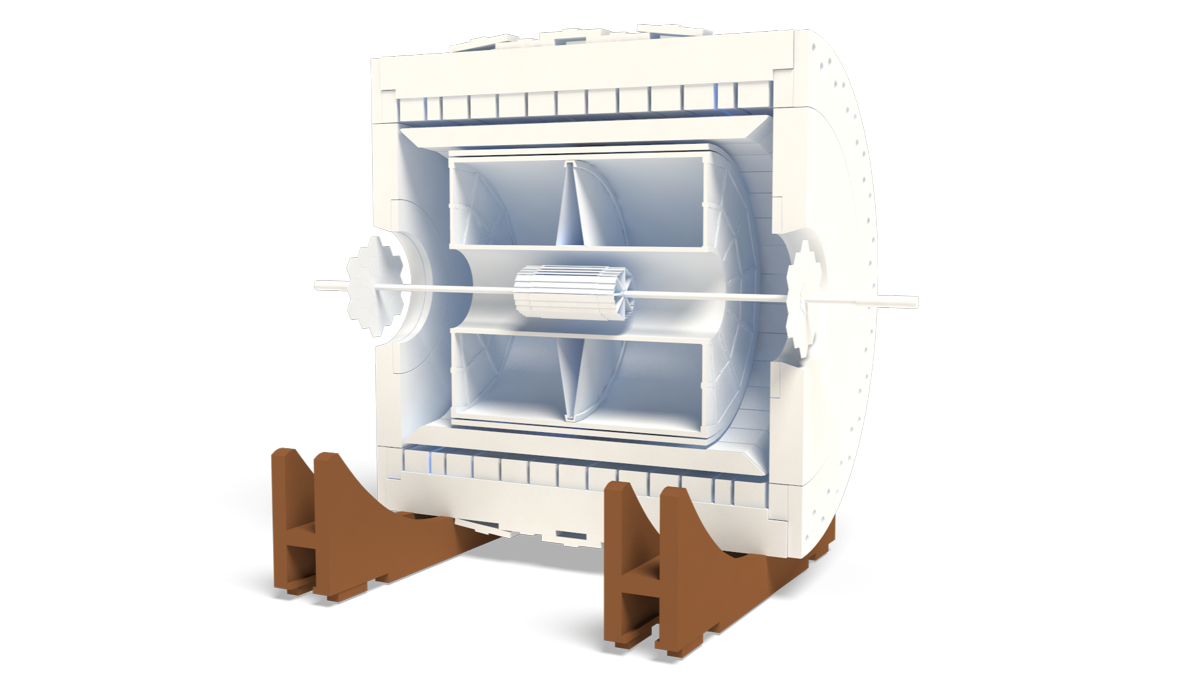
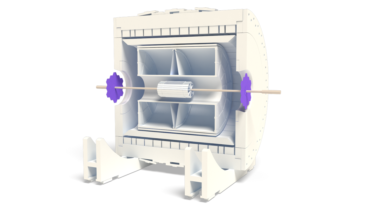
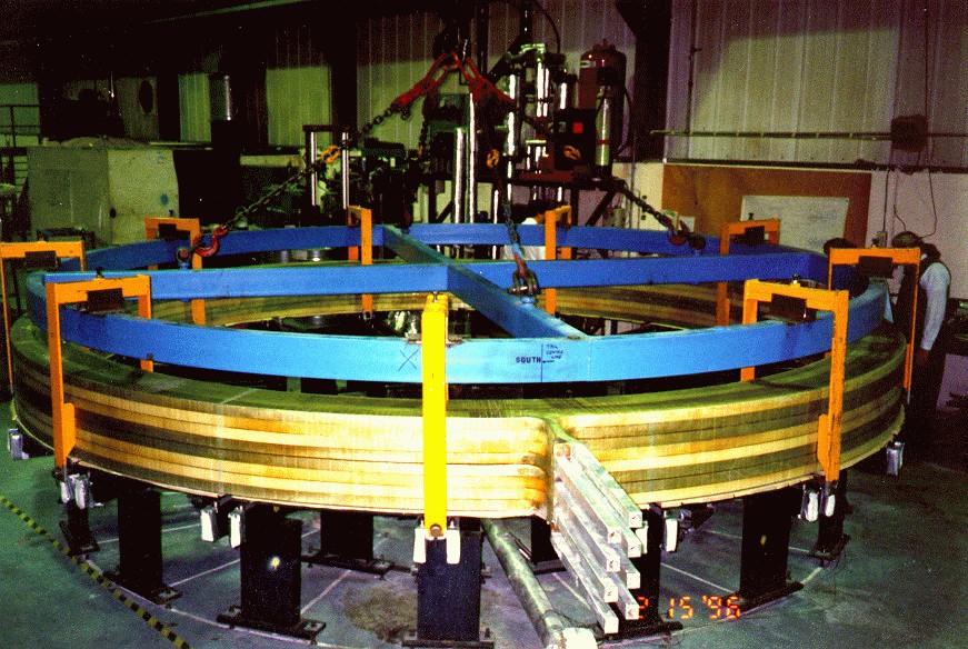
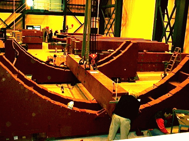
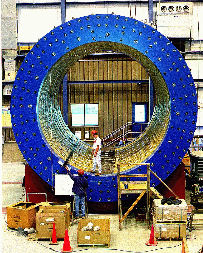
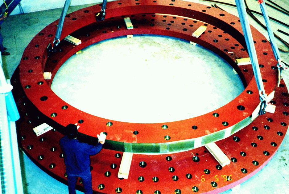
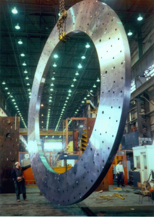
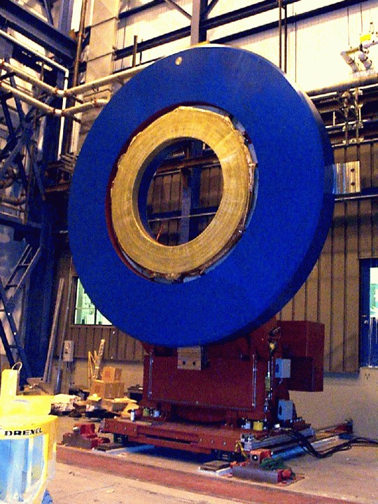
The Solenoidal Magnet steel is a cylindrical structure weighing 1,100 tons on axis with the collider beam and consisting of 30 flux return bars (backlegs), four end rings, two pole pieces, and support structures. The 6.85 m long flux return bars are trapezoidal in cross-section, and weigh 18 tons each. They form the outer cylinder wall encompassing the main and space trim excitation coils and are attached to an inner and outer end ring pair at each end of the magnet. The inner rings have a 5.27 m I.D. with thirty chord surfaces on the 6.28 m O.D. to control the azimuth location of each flux return bar, with an axial thickness of 285 mm, weighing 25 ton each. The outer rings are the structural connection between the ends of the flux return bars and the outer face of each inner ring and have the same I.D. as the inner rings with a 7.32 m O.D. and 203 mm axial thickness, weighing 35 ton each. Each pole piece weighs 73 ton and is on axis with, and supported by, the end rings and has a conical I.D. at η = 2 with a 525 mm axial thickness a 5.06 m O.D. and a counter bore on the inner face for the pole tip trim excitation coil. A 107 mm annular gap exists between end ring I.D. and pole piece O.D. for utility routing to internal detector elements.
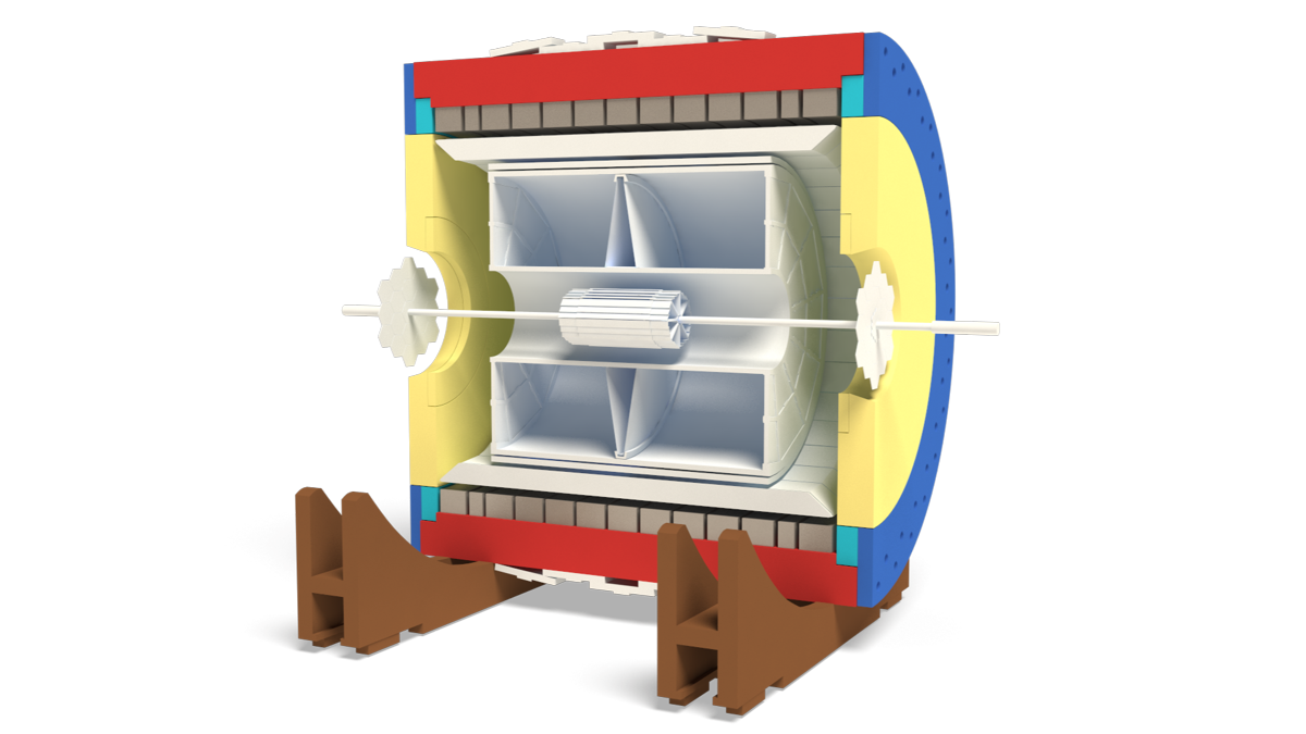
The main support structure consists of two cradles weighing 36 tons each supporting the lower nine flux return bars of the magnet cylindrical yoke. The main support structure is on Hillman Roller systems and hydraulic jacks and is supported and guided on two rails embedded into the floor, thus allowing the magnet to be moved via hydraulic jacks between experimental hall and assembly building. In addition to the main support structure there are two external pole piece support structures weighing 100 tons each that permit removal of the pole pieces for installation or maintenance of internal detector elements. The magnetic field quality required that deflections in the magnet structure be minimized to less than 1 mm. This was accomplished with precise fabrication of magnet components and the use of high strength bolted and pinned connections between mating components.
Barrel ElectroMagnetic Calorimeter (BEMC)
The Barrel Electromagnetic Calorimeter (BEMC) is a lead-scintillator sampling calorimeter surrounding the STAR TPC.
STAR, which is nominally a slow detector, utilizes the BEMC to trigger on and study rare, high PT Tprocesses (jets, leading hadrons, direct photons, heavy quarks) and provide large acceptance for photons, electrons, π0 and η mesons in systems spanning polarized pp through AuAu collisions. Other applications include general event characterization in heavy ion collisions including ultra peripheral collisions. In the next sections we will describe the BEMC in more detail.
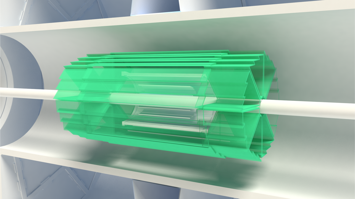
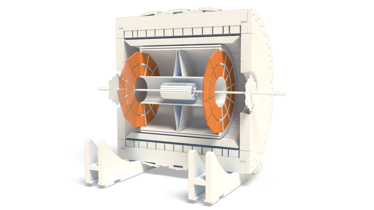
The calorimeter is located inside the magnet coil and surrounds the TPC (Fig. 1). It covers a pseudorapidity range of |η| < 1 and full azimuth, matching the TPC acceptance. The calorimeter is divided in two adjacent barrels, one positioned at the West half of the STAR detector (0 < η < 1) and the other one at the East half (–1 < η < 0). Each half barrel has a length of 293 cm, an inner radius of 223 cm and an outer radius of 263 cm.
Fig. 1. Cross-sectional and longitudinal view of the STAR detector showing the layout of the BEMC
The half barrel is azimuthally segmented into 60 modules. Each module is approximately 26 cm wide and covers 6 degrees (17 mrad) in azimuth and one unit in pseudorapidity. The active depth is 23.5 cm to which is added 6.6 cm of structural elements at the outer radius. The longitudinal and transverse segmentation of a module is shown in Fig. 2 and the radial structure in Fig 3.
The modules are segmented into 40 projective towers of lead-scintillator stacks, 2 in φ and 20 in η. A tower covers 0.05 in Δφ and 0.05 in Δη. Each calorimeter half is thus segmented into a total of 2400 towers.
Each tower consists of an inner stack of 5 layers of lead and 5 layers of scintillator and an outer stack of 15 layers of lead and 16 layers of scintillator. All these layers are 5 mm thick, except the innermost two scintillator layers which are 6 mm thick. A separate readout of these latter two layers provides the calorimeter preshower signal. A Shower Maximum Detector (SMD) is positioned between the inner and outer stacks at a depth of appoximately 5 radiation lengths. The whole stack is held together by mechanical compression and friction between layers.
Fig 2. Side view of a calorimeter module and top view of a scintillator plate segmented into 20 x 2 towers
Fig 3. Transverse view of a calorimeter module showing the inner layer of lead/scintillator stacks, the shower maximum detector (SMD), the outer layer of stacks and the carriage structure at the outer radius of the BEMC barrel
The plastic scintillator layers are machined as “megatiles”, covering the full length and width of a module. These megatiles are segmented into 40 optically isolated tiles, as shown in the top diagram of Fig 2. The optical separation between the individual tiles is achieved by 95 % deep cuts in the scintillator filled with opaque epoxy. The optical crosstalk between adjacent tiles is reduced to a level of 0.5 % by painting a black line on the surface opposite to the isolation groove.
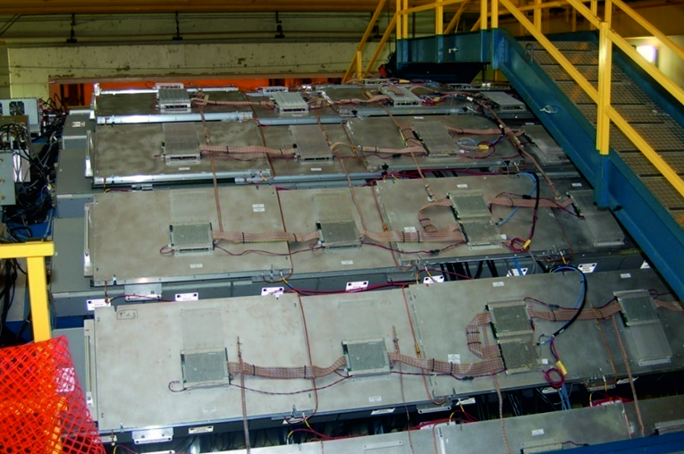
The optical readout scheme is shown in Fig 4. The signal from each tile is collected by a wavelength shifting (WLS) fiber embedded in a σ-groove in the tile. The WLS fibers run along the outer surface of the stack and terminate in an optical connector mounted at the back-plate of the module. From the back-plate, 2.1 m long fibers run through the STAR magnet structure to the readout boxes mounted on the outer side of the magnet. In these boxes the 21 fibers from the tiles of one tower are connected to a single photomultiplier tube (PMT). The PMTs are powered by Cockroft-Walton bases that are remotely controlled over a serial communication line by the slow control software.
From layer by layer tests of the BEMC optical system, together with an analysis of cosmic ray and test beam data, the nominal energy resolution of the calorimeter is estimated to be δE / E = 15 % / √(E[GeV]) ⊕1.5 %.

Fig 4. Optical readout scheme of a BEMC tower
Shower Maximum Detector
The Shower Maximum Detector (SMD) is a multi-wire proportional counter with strip readout. It is located at a depth of approximately 5.6 radiation lengths at η = 0 increasing to 7.9 radiation lengths at η = 1, including all material immediately in front of the calorimeter.
The purpose of the SMD is to improve the spatial resolution of the calorimeter. This is necessary because the transverse dimension of each tower (about 10 × 10 cm2) is much larger than the lateral spread of an electromagnetic shower. The improved resolution is essential to separate the two photon showers originating from the decay of high momentum π0 and η mesons.
The layout of the SMD is shown in Fig 5. Independent cathode planes with strips along η and φ directions allow the reconstruction of a two dimensional image of a shower. The coverage in Δη × Δφ is 0.0064 × 0.1 for the η strips and 0.1 × 0.0064 for the φ strips. There are a total of 36000 strips in the full detector.
Beam test results at the AGS have shown that the SMD has an approximately linear response versus energy. The energy resolution in the η coordinate (front plane) is approximately σE / E = 86 % / √(E[GeV]) ⊕ 12 % whereas that in the φ coordinate (back plane) is worse by about 3–4 %. The position resolution is σ(rφ) = 5.6 / √(E[GeV]) ⊕ 2.4 mm and σ(z) = 5.8 / √(E[GeV]) ⊕ 3.2 mm.
Preshower Detector
The first and second scintillating layers of each calorimeter module are used as a preshower detector (PSD). To achieve a separate readout of these layers two WLS fibers are embedded instead of one in the σ-groove of each tile. This additional pair of fibers from the two layers illuminate a single pixel of a multi-anode PMT. A total of 300 16-pixel multi-anode PMTs are used to provide the 4800 tower preshower signals.
The preshower detector was fully instrumented and read out only in 2006 so that it could not be used in the present analysis.
Fig 5. Schematic illustration of the SMD showing in the top figure a three dimensional view of the extruded aluminium profile containing the anode wires and the two read-out pad planes running parralel and perpendicular to the wires. The profile of a BEMC shower as recorded in the two SMD pad planes is shown by the histograms. The bottom plot shows a transverse view of the aluminium extrusion, the anode wires and the pad planes
BEMC electronics
The calorimeter is a “fast” detector in STAR so that its ADCs can be read out on each RHIC bunch crossing. The calorimeter data is also used in the STAR level-0 trigger, in the form of the “High Tower” and “Patch Sum” trigger primitives.
The level-0 HighTower trigger used in this analysis is a requirement that the energy deposited in any single calorimeter cell in the event exceeds a given threshold. This allows to enhance the statistics at the high energy part of the spectrum.
The complete description of the BEMC electronics operation is given in Appendix A.
Time Of Flight (TOF)
General infoTime Projection Chamber (TPC)
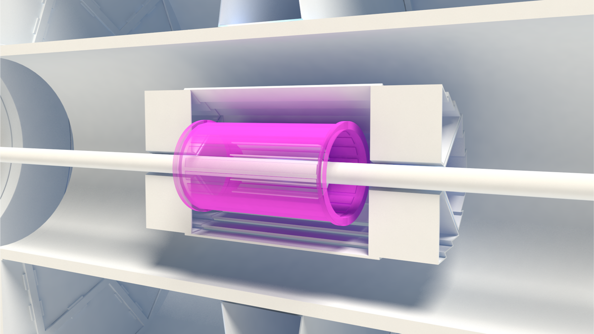
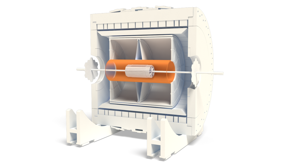
The STAR Time Projection Chamber (TPC) is used to record the collisions at the Relativistic Heavy Ion Collider (RHIC). The TPC is the central element in a suite of detectors that surrounds the interaction vertex. The TPC provides complete coverage around the beam-line, and provides complete tracking for charged particles within ±1.8 units of pseudo-rapidity of the center-of-mass frame. Charged particles with momenta greater than 100 MeV/c are recorded. Multiplicities in excess of 3,000 tracks per event are routinely reconstructed in the software. The TPC measures 4 m in diameter by 4.2 m long, making it the largest TPC in the world.
TPC function
• Large acceptance gas detector– |η| < 1.8
– Full azimuthal coverage
• Momentum reconstruction– Tracking with design hit position resolution ~500 µm
• Pid using dE/dx– Design resolution: 7 %
| Item | Dimension | Comment |
|---|---|---|
| Length of the TPC | 420 cm | Two halves, 210 cm long |
| Outer Diameter of the Drift Volume | 400 cm | 200 cm radius |
| Inner Diameter of the Drift Volume | 100 cm | 50 cm radius |
| Distance: Cathode to Ground Plane | 209.3 cm | Each side |
| Cathode | 400 cm diameter | At the center of the TPC |
| Cathode Potential | 28 kV | Typical |
| Drift Gas | P10 | 10% methane, 90 % argon |
| Pressure | Atmospheric + 2 mbar | Regulated at 2 mbar above Atm. |
| Drift Velocity | 5.45 cm/μs | Typical |
| Transverse Diffusion (σ) | 230 mm/√cm | 140 V/cm & 0.5 T |
| Longitudinal Diffusion (σ) | 360 mm/√cm | 140 V/cm |
| Number of Anode Sectors | 24 | 12 per end |
| Number of Pads | 136,608 | |
| Signal to Noise Ratio | 20 : 1 | |
| Electronics Shaping Time | 180 ns | FWHM |
| Signal Dynamic Range | 10 bits | |
| Sampling Rate | 9.4 MHz | |
| Sampling Depth | 512 time buckets | 380 time buckets typical |
| Magnetic Field | 0, ±0.25 T, ±0.5 T | Solenoidal |
Fig.1 The STAR TPC surrounds a beam-beam interaction region at RHIC. The collisions tplace near the center of the TPC
STAR detector
• 0.5 Tesla magnet– 0.25 for year 1
• Trigger– CTB
– ZDC
– Level 3
• Year 1 detectors– TPC
– RICH
– 1 SVT ladder
TPC gas volume
The gas system circulates the gas in the TPC and maintains purity, reducing electro negative impurities such as oxygen and water which capture drifting electrons. To keep the electron absorption to a few percent, the oxygen is held below 100 parts per million and water less than 10 parts per million.
• Gas: P10 (Ar-CH4 90 %–10 %), 1 atm
• Drift voltage: –31 kV
Pad readout
The readout system is based on Multi-Wire Proportional Chambers (MWPC) with readout pads. The drifting electrons avalanche in the high fields at the 20 µm anode wires providing an amplification of 1000 to 3000. The positive ions created in the avalanche induce a temporary image charge on the pads which disappears as the ions move away from the anode wire. The image charge is measured by a pream-plifier/shaper/waveform digitizer system. The induced charge from an avalanche is shared over several adjacent pads, so the original track position can be reconstructed to a small fraction of a pad width. There are a total of 136,608 pads in the readout system.
Fig.2
Electronic readout
• FEE, custom design IC: SAS + SCA (512 time bins)– Readout 140 K channels, i.e. 70 M pixels
• Readout board– Carry ~1000 Channels to DAQ
Fig.3
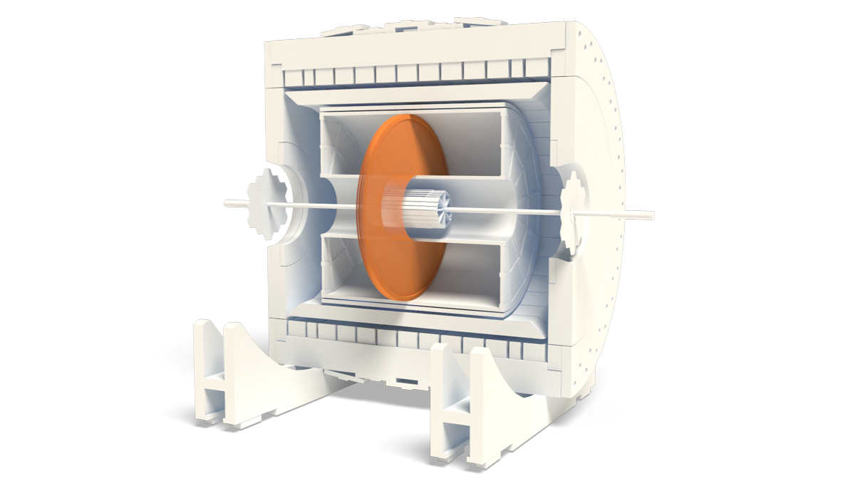
The Time Projection Chamber consists of a gas filled sensitive volume, usually with a central cathode that divides the volume into two identical halves. Each side has an anode with a readout system. The cathode is at a high potential that results in a field strength of some 100 V/cm while the anode is at ground potential (typically, this leads to a potential of some 10 kV at the cathode). In 4π-detectors (detectors that cover nearly the whole solid angle) at high energy physics experiments, the drift volume is usually cylindrical and the beam pipe goes through the rotation axis of the TPC with the interaction point being at the center.
A charged particle traversing the gas volume of the TPC will ionizes the atoms of the gas mixture (usually around 90 % noble gas and 10 % quencher gas) along its trajectory, see point 1 in a figure bellow. A high electric field is applied between the endplates of the chamber. The released electrons drift in this field towards the anode, see point 2 in a figure bellow.
To be able to measure the position of the particle trajectory as accurately as possible, the electric field has to be very homogeneous. This can be achieved by a field cage, which usually consists of conducting rings around the cylinder. These rings divide the potential from the cathode stepwise down to the anode. Additionally, a high magnetic field parallel to the electric field is used to “bend” the trajectory of the particle on a spiral track due to the Lorentz force. This gives the possibility to calculate the momentum of the particle from the knowledge of the curvature and the B-field.
It the anode plane, the electrons can be detected on the readout plane which is segmented in the directions perpendicular to the drift direction, see point 3 in a figure bellow. As the electron signal from the primary ionization process is only of the order of 100 electrons per centimeter, the signal needs to be amplified before being detectable. Traditionally this has been done within high electric field in vicinity of thin wires.
The rφ position (coordinates perpendicular to the cylinder axis) of the trajectory can be reconstructed directly from the coordinates of its projection on the pad plane. The z position (coordinate along the cylinder axis) is reconstructed from the drift time (time between particle passing the TPC volume and measured signal on the pads). Therefore an external timing information, e.g. from a silicon detector, is needed.
Fig.4 Working principle of a TPC (by O. Schäfer)
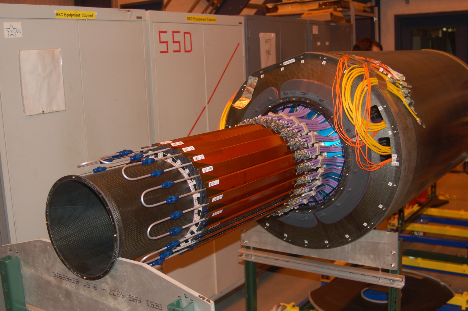
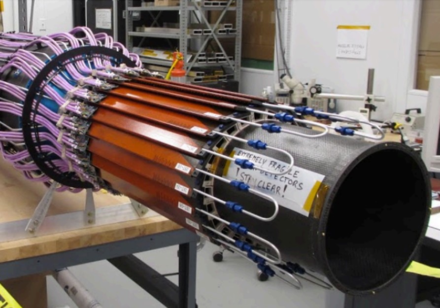
HFT (Heavy Flavour Tracker)
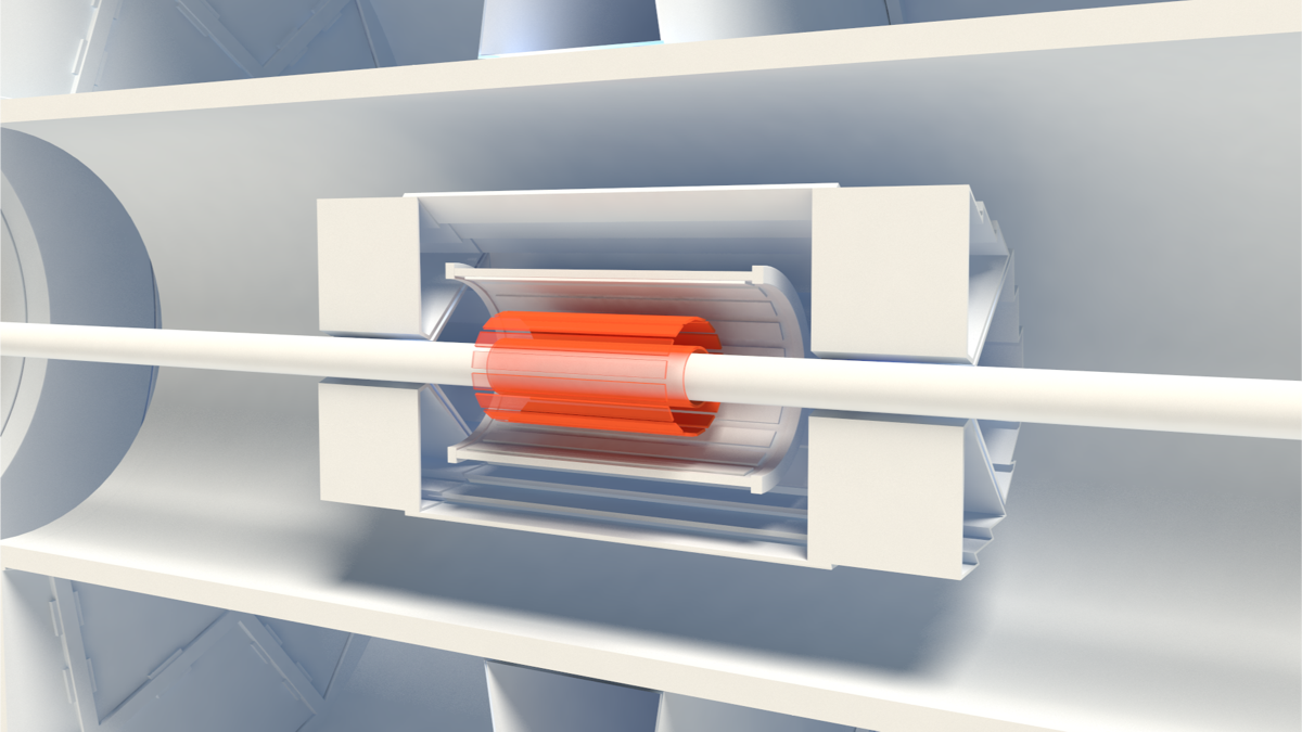
STAR Heavy Flavor Tracker can be enable or enhance many open heavy flavor measurements, by reconstructing open heavy flavor hadrons with displaced decay vertices.
Physics Motivation
• Heavy flavormb,c >> Tc, ΛQCD, mu,d,s
Produced early in initial hard scatterings
Total number conserved in system evolution at RHIC
• However, it’s also difficult to study heavy flavor quarks in experimentsLimited yield comparing with light flavor particles
Large combinatorial background for direct reconstruction of open heavy flavor hadrons without displaced decay vertex reconstruction
Large kinematics smearing for studies with electrons from semi-leptonic decay
• A precision vertex detector will be an important tool to asses HF physics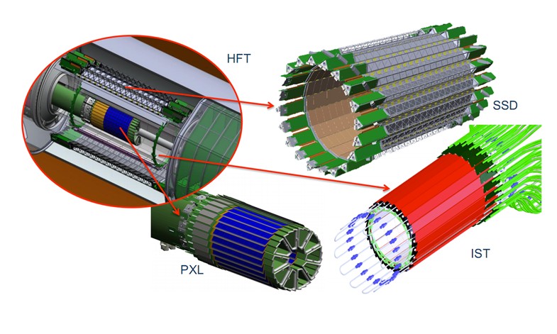
Fig.1 HFT parts
| Sub detector | r (cm) | Sensitive units | σR-φ(μm) | σz(μm) | X/X0 (%) |
|---|---|---|---|---|---|
| Silicon Strip Detector | 22 | 2 side strips with 95 μm pitch | 20 | 740 | 1 |
| Intermediate Silicon Tracker | 14 | 600 μm × 0.6 cm strips | 170 | 1800 | <1.5 |
| PIXEL | 2.5/8 | 18 μm pixel pitch | 12 | 12 | 0.4/layer |
HFT can be used to study heavy flavor production by the measurement of displaced vertices.
• D0 → K-π+– BR = 3.83 % cτ ~120 μm
• Λc+ → p K-π+– BR = 5.0 % cτ ~60 μm
• B mesons → J/ψ + X or e + X– cτ ~500 μm
• Total charm yield → base line for charmonium suppression & coalescence• RCP, RAA of charm and bottom → energy loss in QGP
• Charm (D0) flow → thermalization?
• (cc (D0D0) angular correlation → interaction with the medium
• Λc+/D0 → test coalescence model
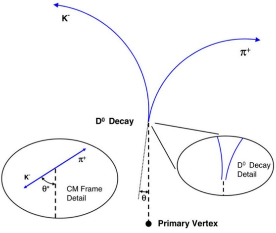
Fig.2 Direct topological reconstruction of Charm
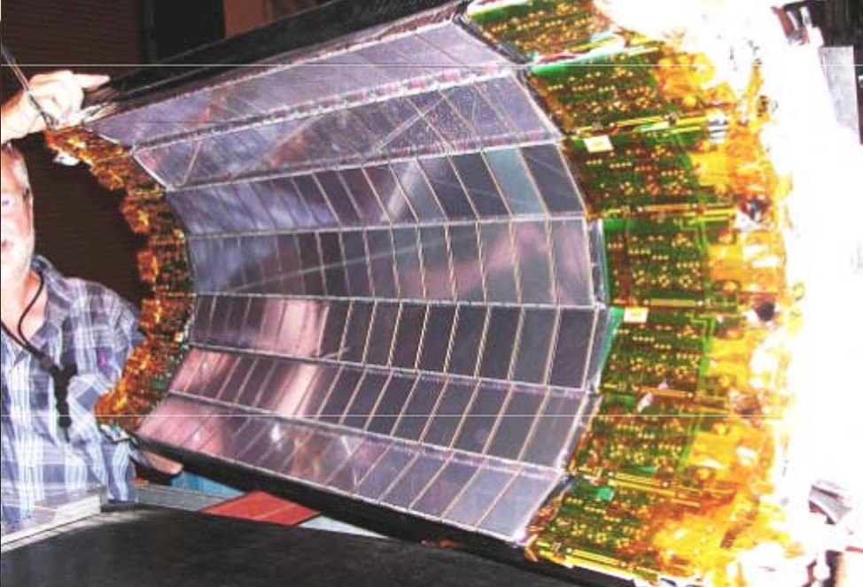
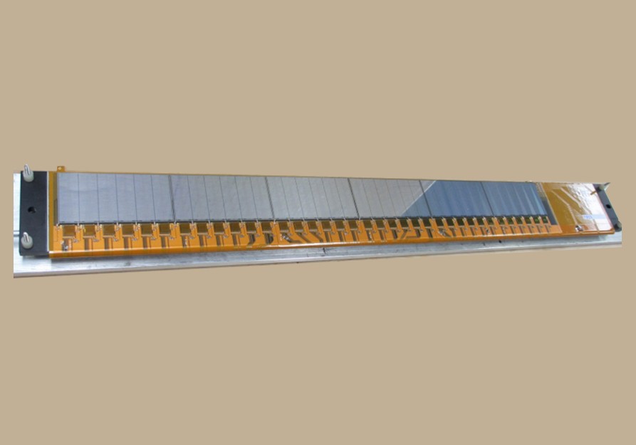
Silicon Strip Detector (SSD)
The task of the Silicon Strip Detector (SSD) and the Intermediate Silicon Tracker (IST) is to guide the track from TPC to the innermost PXL detector with high hit density.
• σr-φ: 20 µm
• σz: 740 µm
• radius: 22 cm
• X/X0: 1 %
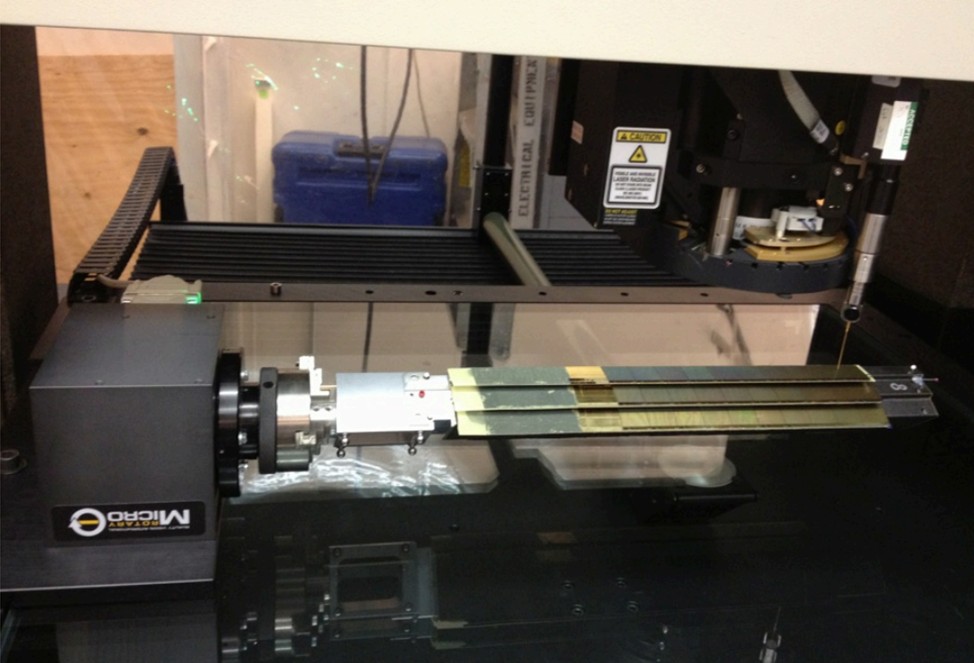
Intermediate Silicon Tracker (IST)
The task of the Intermediate Silicon Tracker (IST) and the Silicon Strip Detector (SSD) is to guide the track from TPC to the innermost PXL detector with high hit density.
Intermediate Silicon Tracker
• single-sided double-metal silicon pad• sensors with 600 μm × 6 mm pitch
• σr-φ: 170 μm σz: 1800 μm
• radius: 14 cm X/X0 < 1.5 %
• See details at poster M-30 by Yaping Wang
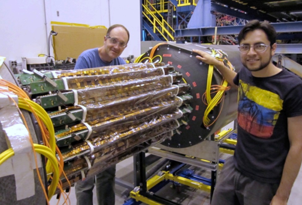
PXL
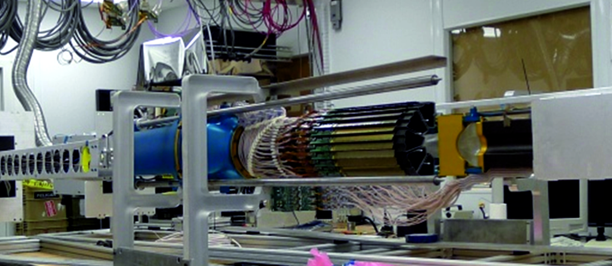
Heavy Flavor Tracker Pixel Detector (HFT PXL) — main tracking detector in STAR — is the first operational vertex detector based on Monolithic Active Pixel Sensors (MAPS) or also called CMOS Pixel Sensors (CPS). CPS developed by PICSEL group of IPHC-Strasbourg (Marc Winter et al.).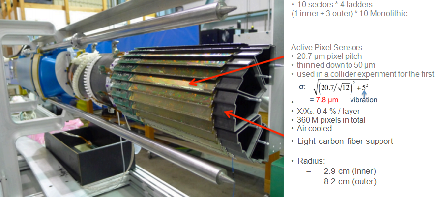
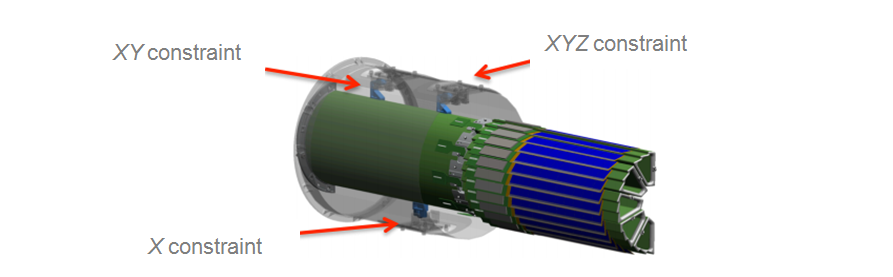
• 3 kinematic mounts locate the PXL half on the PXL supporting tube.
• PXL insertion can be done in ~12 hours, by pushing PXL halves along rails and latching on kinematic mounts.
• 2 sets of PXL detectors and 40 spare ladders are made, to replace damaged detector units when needed.
Over the development time of the PXL detector, improvements in the CMOS available to IPHC lead to important improvements. The available p-epi layer went from 10 Ω cm to 400 Ω cm, that is the p-epi is less heavily doped and consequently the depletion region thickens. This improves the signal to noise because C is smaller resulting in better signal to noise (remember ΔV = ΔQ/C). This and the reduced charge collection time improves radiation hardness. Reducing the charge collection time means less probability for electrons to be trapped on the radiation induced defects. Slow electrons in the diffusion region are more likely to be trapped than the fast electrons in the depleted drift region.
1. Marc Winter’s talk: “CMOS Pixel Sensors Developed for the ALICE-ITS Upgrade” Workshop on CMOS Active Pixel Sensors for Particle Tracking (CPIX14) 15–17 September 2014, University of Bonn (http://indico.cern.ch/event/309449/session/20/contribution/9/material/slides/)
2. The ALICE Collaboration, J. Phys. G: Nucl. Part. Phys. 41 (2014) 087002, 2.5.4 ALPIDE, p. 22
BBC (Beam Beam Counter)
At the Brookhaven National Laboratory (BNL) Relativistic Heavy Ion Collider (RHIC) the Beam-Beam Counter (BBC) array for the Solenodial Tracker at RHIC (STAR) is a very versatile tool for polarized proton beam diagnostics. The BBC setup provides an excellent minimum bias trigger; and for hits on the inner annuli of six hexagonal scintillator tiles the BBC coincidence trigger with a suitable algorithm has a quite large single spin analyzing power ˜8×10⁻³ for 100 GeV polarized proton -100 GeV polarized proton collisions. The STAR BBC is a very effective local polarimeter at these energies. For 100 GeV p⃗-100 GeV p⃗ running in 2006 the BBC measured single spin asymmetries to a statistical accuracy of better than 2% for a data run of 20-30 minutes; and these measurements were quite robust. For fills with a duration of at least six hours these STAR BBC asymmetry measurements were used to study the time dependence of the polarization for 100 GeV proton beams in the RHIC rings. The decrease of the polarization is quite small, <0.01PB per hour.MTD
A large area Muon Telescope Detector (MTD) at mid-rapidity will provide excellent muon identification and trigger capabilities at mid-rapidity in the high-luminosity era at RHIC. This novel and compact detector can provide crucial measurements for many exciting physics perspectives. We can measure and separate different Upsilon states and measure J/ψ over a broad transverse momentum range through di-muon decays to study color screening features. The measurement of e-muon correlations can distinguish heavy flavor contributions from initial lepton pair production.
• A detector with long-MRPCs will cover STAR magnet backlegs and leave the gaps in between uncovered
• Acceptance: 45 % • 2π at |η| < 0.5
• 118 modules, 1416 readout strips, 2832 readout channels
• Strip length: 87 cm
• Each strip is read out from both ends
• 10% (13 modules) of the full system installed
• Intrinsic timing resolution: <100 ps
• Spatial resolution: ~1 cm
Multi-gap Resistive Plate Chamber (MRPC)
• Gas detector, avalanche mode
• Long-MRPC detector technology, electronics same as used in STAR-TOF
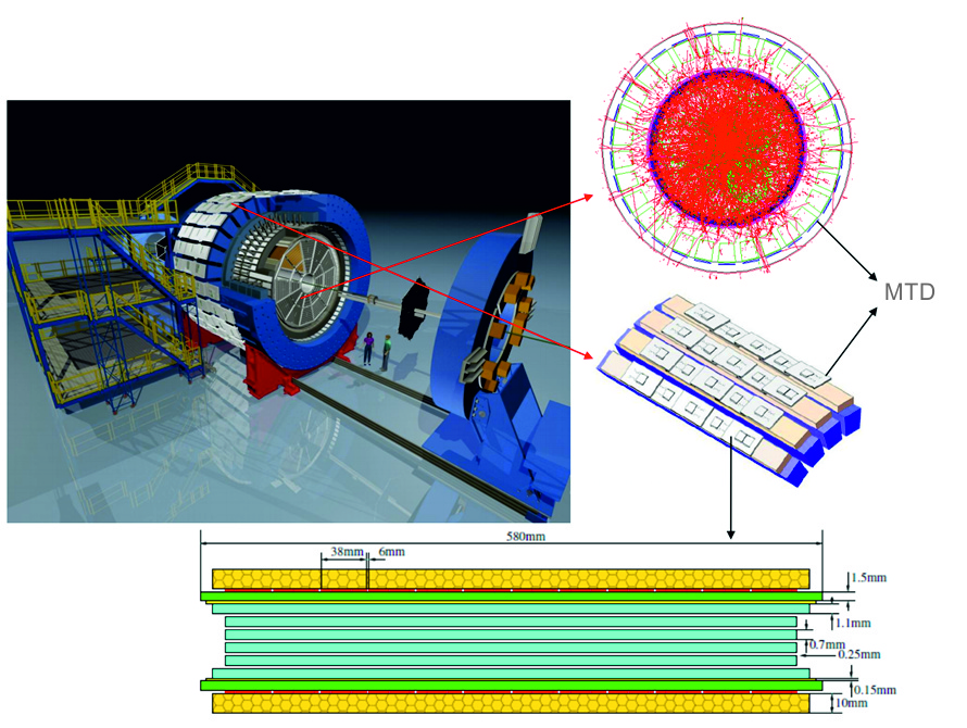
Fig.1 End view of an LMRPC module for the full MTD
• Di-muon pairs from QGP thermal radiation, quarkonia, light vector mesons,resonances in QGP, and Drell-Yan production
• Single muons from the semi-leptonic decays of heavy flavor hadrons
• Advantages over electrons: no γ conversion, much less Dalitz decay contribution, less affected by radiative losses in the detector materials
• Excellent mass resolution, separate different upsilon states
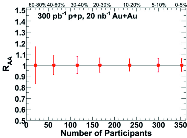
Fig.2 Simulation results of ϒ(1S + 2S + 3S) RAA versus Nparticipant
• Trigger capability for low to high pT J/ψ in central Au+Au collisions
• Distinguish heavy flavor decayed lepton pairs from initial lepton pair production
MTD trigger capabilities
• Cosmic trigger: coincidence with 2 TOF sectors, trigger for cosmic-ray events
• MTD&VPD(vertex position detector) trigger: coincidence with minbias trigger, trigger for MTD&VPD minbias events
• MTD&BHT(EM calorimeter high tower) trigger: coincidence with hits on energy deposition in EMC, trigger for events with e-μ
• MTD 2hits trigger: require at least two hits on MTD, trigger for events with μ-μ